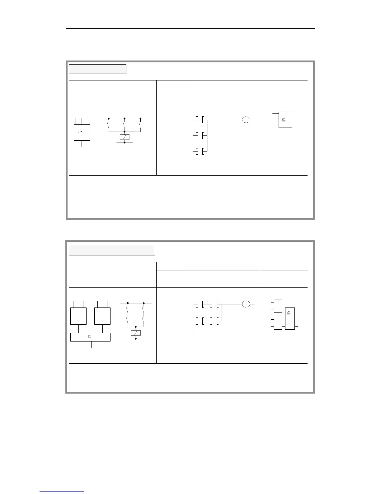
Logic operations
(continued)
O
I 1.2
O
O
I 1.7
I 1.5
= Q3.2
I 1.2
I 1.7
I 1.5
Q 3.2
state "0" simultaneously
Output Q 3.2 is "1" when at least one of the inputs is "1"
I 1.5I 1.7I 1.2
Q 3.2
I 1.2 1.7 1.5
Q 3.2
I 1.2
I 1.7
I 1.5
Q 3.2
1
1
Logical/circuit diagram
STEP 5 representation
Ladder Control system
Statement
list
OR operation
diagram flowchart
Output Q 3.2 is "0" when all inputs have the signal state
The number of scans and sequence of programming is optional
I 1.5 I 1.6
I 1.4
Q 3.1
Q 3.1 is "1" when at least one AND condition is satisfied
I 1.1
I 1.7
Q 3.1
&
I 1.6
I 1.5
Q 3.1
I 1.3
I 1.4
I 1.5 I 1.6
Q 3.1
&
I 1.4 I 1.3
&
A
I 1.5
A
A
I 1.6
I 1.3
= Q3.1
O
A I 1.4
I 1.3
I 1.1
I 1.7
&
1
1
Logical/circuit diagram
STEP 5 representation
Ladder Control system
Statement
list
AND-before-OR operation
diagram flowchart
Q 3.1 is "0" when no AND condition is satisfied
Programming Examples in the STL, LAD and CSF Methods of Representation
CPU 948 Programming Guide
C79000-G8576-C848-04
3 - 35