5.4.3
Example of Error Diagnosis
using the ISTACK
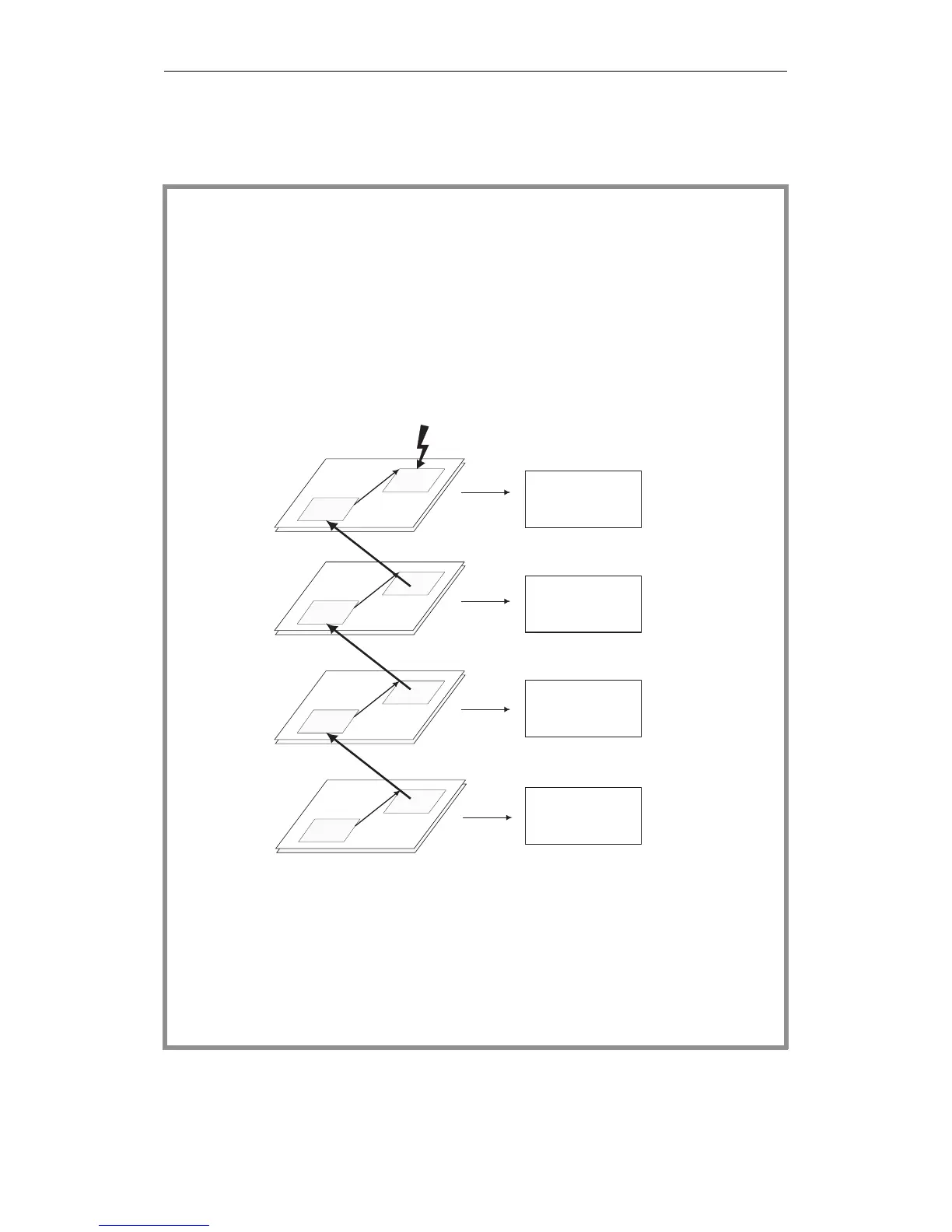
Fig. 5-3 illustrates the structure of the ISTACK in conjunction with the
interruptions that have occurred.
- The program execution level CYCLE (
OB 1) is interrupted by an interrupt.
- Following this, the program processing level interrupt is activated and
OB 3 called.
- The occurrence of a timed interrupt means that the INTERRUPT level is
exited and the TIMED INTERRUPT level activated and
OB 13 processed.
- An incorrect addressing operation leads to the activaton of the ADF
level where
OB 25 is processed. In the error handling program, the user
has programmed a stop operation (STS) the CPU aborts program execution.
Before the final transition to the stop mode, a total of four different
program execution levels were interrupted. If you now display the ISTACK on
the PG, you will obtain a
four-level ISTACK, at the top the ISTACK with
depth 01, with the ID of the
last interrupted program execution level (=
ADF). You can page down through the ISTACK until you reach depth 04,
representing the CYCLE program execution level, which was interrupted
first.
STS
ADF
STS
X
X
Depth 04
Program execution levels ISTACK
Depth 03
Depth 02
Depth 01
CYCLE
TIMED INTERRUPTS
INTERRUPT
ADF
OB 1
OB 3
OB 13
OB 25
Fig. 5-3 Example of evaluating the ISTACK
Control Bits and Interrupt Stack
CPU 948 Programming Guide
C79000-G8576-C848-04
5 - 19