3. Enter the values by pressing the enter key on the PG.
The PG then generates DB 1.
4. Transfer DB 1 to the CPU.
Note
Entry of the timer field length is ignored! This parameter must be
specified in DX 0 (see Chapter 7).
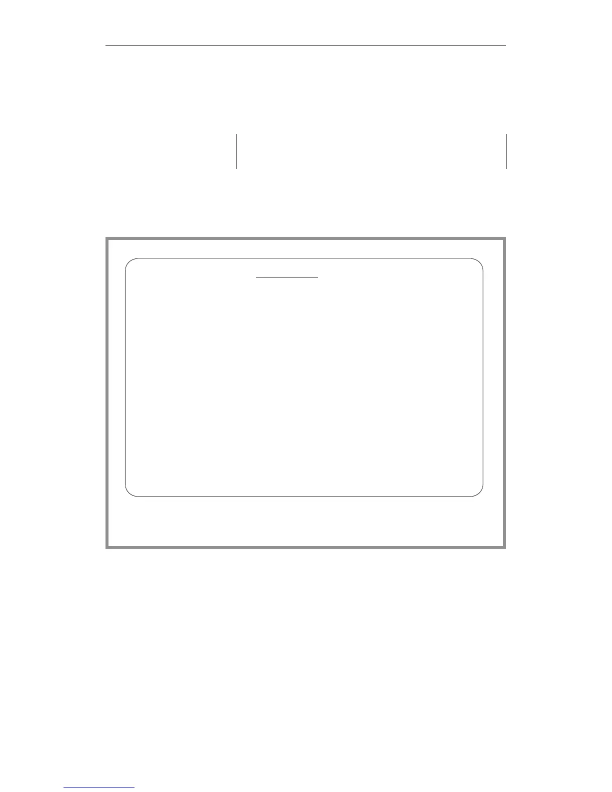
Example of the DB 1 screen
form
Editing DB 1 as a data block
1. Write the DB 1 start ID in data words 0, 1 and 2:
DW 0: KH = 4D41 (’M’ ’A’)
DW 1: KH = 534B (’S’ ’K’)
DW 2: KH = 3031 (’0’ ’1’)
DB 1
0,
1, 2,
3,
7,
10,
2, 4,
12,
0,
50,
51,
60,
70,
72,
100,
,
,
,
,
,
,
,
,
,
,
,
,
,
,
,
,
,
,
,
,
,
,
,
,
,
,
,
,
,
,
,
,
,
,
,
,
,
,
,
,
,
,
,
,
,
,
,
,
,
,
I/O assignment:
Digital inputs:
Digital outputs:
IPC flag inputs:
IPC flag outputs:
Timer field length:
Fig. 10-3 PG screen form for generating DB 1
Multiprocessor Mode
CPU 948 Programming Guide
10 - 10 C79000-G8576-C848-04