Installing the Control Unit
43 |
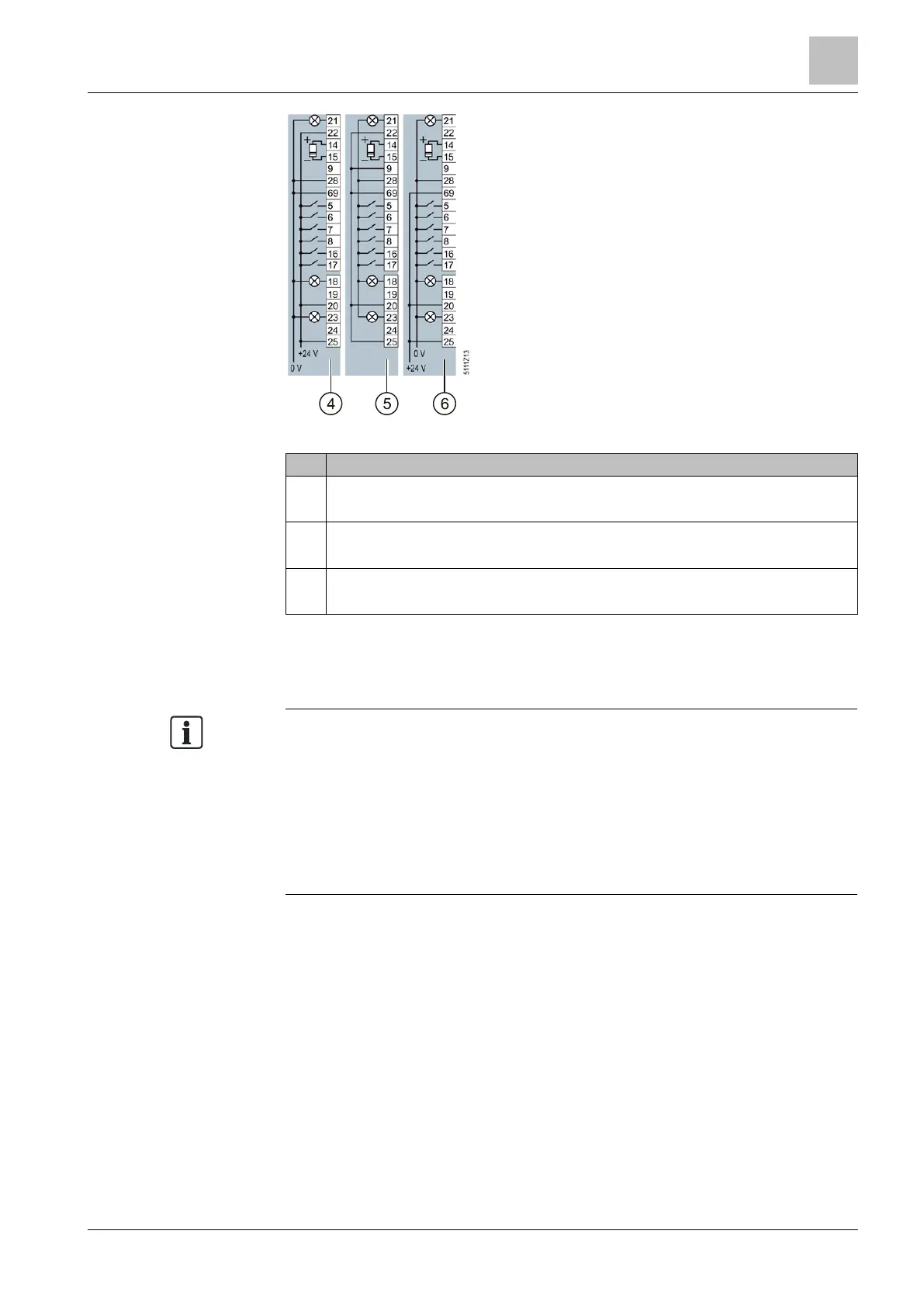
Figure 19: Terminal strips 4-6
4
Wiring when using external power supplies.
Connecting a contact switching to P.
5
Wiring when using the internal power supplies.
Connecting a contact switching to M.
6
Wiring when using external power supplies.
Connecting a contact switching to M.
5.4.2.2 Wiring terminal strips
The inputs and outputs of the variable speed drive and the fieldbus interface have
specific functions when set to the factory settings.
When you put the variable speed drive into operation, you can change the
function of each of its inputs and outputs and the setting of the fieldbus interface.
To make the setting process easier, the variable speed drive has various
predefined assignments (macros).
For further information about terminal strip preassignments (macros), please refer
to Chapter 4.6 in the Operating Instructions for the Control Unit (A5E34257946A
AB).
To connect up the terminal strips of the variable speed drive, proceed as follows:
The Control Unit has been mounted on the Power Module (Chapter Installing
the Control Unit [➙ 40]).
The device is de-energized.
1. Prepare the cables you will need (Chapter Overview of motor cable lengths and
cross sections [➙ 33]).
2. Remove the last 10 mm (approx.) of the cable insulation.
3. Using the screwdriver, press on the operator control of the spring-loaded
terminal hard enough to open the terminal.
4. Insert the cable into the terminal as far as it will go and remove the screwdriver.
5. Ensure that the cable is securely connected by pulling on it lightly.

 Loading...


