EMC-compliant installation (examples)
| 98
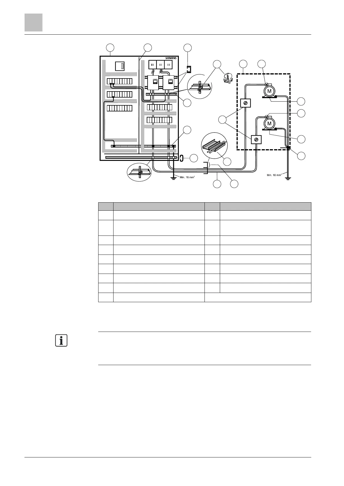
Figure 21: Connection of IP20 devices
1
Cabinet
10
Metal cable duct with partition
2
Metal partition
11
Connect cable shields continuously at
isolator switch
3
C-section mounting rail
12
Monoblock
4
Shield connection clamp
13
Metal cable gland
5
Shielding bus
14
Supply air
6
Clamping rail
15
Metal cable gland
7
Strain relief rail
16
Discharged air
8
Motor cable (shielded)
17
Potential bonding
9
Signal and control cables (shielded)
Using two examples, the following diagram shows the EMC-compliant installation
of the Power Module with and without shield plate.
You must use the shield plate to achieve EMC-compliant installation of devices in
frame sizes FSA to FSC.
The shield of the control cable must be attached to both the shield plate of the
Control Unit and the shield plate of the Power Module.
2
3
6
7
8
9
10
1
5
11
12
13
14
15
4
16
17
F1 F2
G120P
G120P
F3

 Loading...


