EMC-compliant installation (examples)
49 |
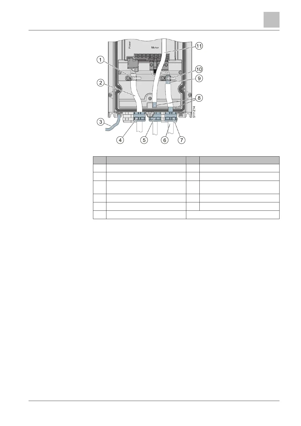
Figure 24: EMC-compliant wiring IP55
1
Strain relief 7 EMC gland (essential for Class B filters)
2
Line supply cable, unshielded 8 Shielding
3
Good conductive connection for high-
frequency EMC interference
9 Motor cable shield
4
Standard cable gland 10 Shield bonded over large area
5
EMC gland 11 Control Unit control cable
6
Shielded motor cable
● Use a shielded cable for terminal wiring of the Control Unit.
● Use either the screening termination kit of the Control Unit or an EMC cable
gland to bond the shield.
● Expose the motor cable shield at the point where the cable is fed through the
base plate and ensure that it is in complete contact with an EMC cable gland. It
is important for the shield to be fed through the cable gland and then to be
connected at the designated place inside the enclosure once again. This
ensures that both the gland plate and the enclosure are in contact with the
shield.
● Feed the motor cable through the right-hand opening in the gland plate.

 Loading...


