EMC-compliant installation (examples)
| 98
1
Expose the cable shield
2
Press cable shield onto the shield/mounting plate
3
Shield plate
4
Mounting plate
EMC-compliant wiring for Power Modules with degree of protection
IP55
Variable speed drives with degree of protection IP55 are suitable for installation
outside a control cabinet.
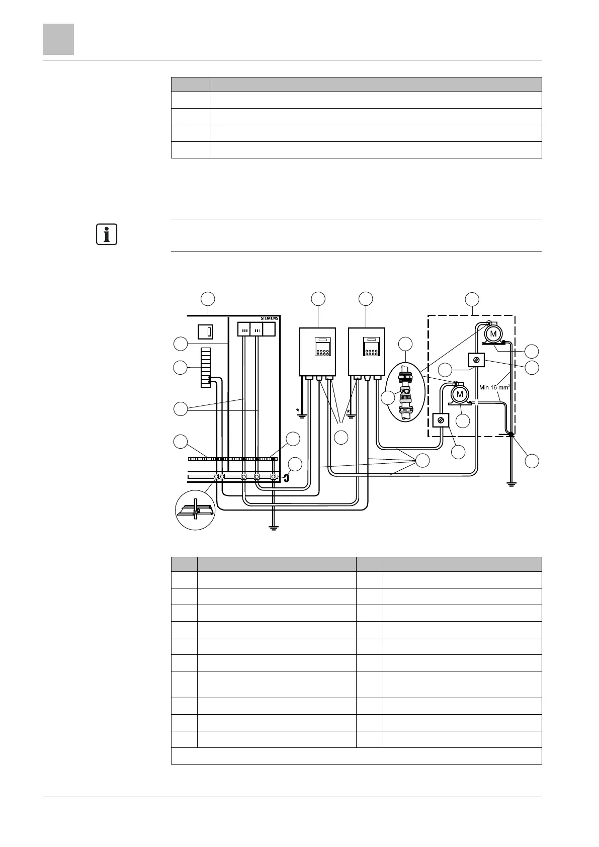
The diagrams below show examples of EMC-compliant installation for devices with
degree of protection IP55:
Figure 23: Connection of IP55 devices
1
Cabinet
11
Metal cable gland
2
Metal partition
12
Shielding
3
I/O modules
13
Shielded cables
4
Supply cable (unshielded)
14
Service switch
5
Connecting terminals
15
Discharged air
6
Strain relief rail
16
Connect cable shield continuously
7
Clamping rail and equipotential bonding
busbar
17
Monoblock
8
Supply air
18
Supply air
9
Cable gland
19
Service switch
10
Discharged air
20
Potential bonding
* All equipotential bonding cables must have a cross section of at least 16 mm
2
.
BMS
F1 F2
G120P/ IP55
G120P/ IP55
*
*
#
2
3
5
7
9
12
13
14
15
17
11
19
16
8
10
1
4
6
18
20

 Loading...


