Service, maintenance and fault rectification
| 98
8.3.3.1 Tests without a power supply
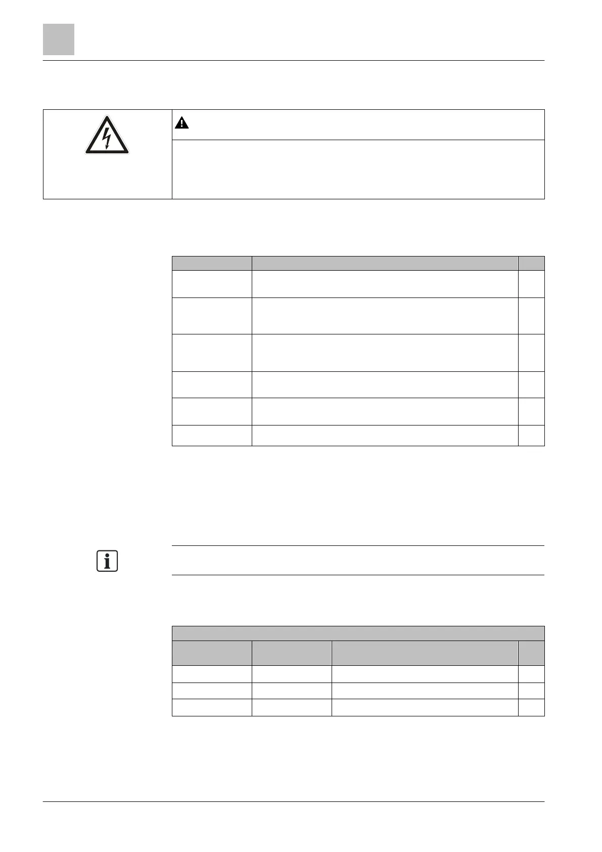
Danger due to electric current!
If the terminals are not accessible externally, do not open the device because you
will be exposed to a great risk and this will invalidate the warranty.
● In this case, contact your local Siemens branch office.
Preliminary tests
Disconnect the
power supply
Ensure that the drive is disconnected from the line supply.
Safeguard Take measures (a mechanical maintenance switch, for example) to
prevent the variable speed drive and the connected motor
(depending on application) from restarting.
Ensure that there is
no voltage present
at the drive.
1. Measure the voltage between L1/L2 and L3.
2.
Make sure that the system is completely de-energized.
Damage caused by
external factors
Check whether parts are damaged, for example by corrosion, paint,
moisture, oil, dust, powder, etc.
Electrical damage Look for evidence of flashovers or burning at the power terminals.
These are caused by connecting the power cables incorrectly.
Fuses
1. Check the sizes of the fuses.
2. Make sure that they are not "open".
Static check on the drive
The following checks are standard tests. These tests can be performed on most
drives which are designed in accordance with the conventional principle "Rectifier –
DC bus – IGBT bridge". The DC bus terminals of the PM230/G120P device are not
generally used. However, the terminals are accessible on some models.
Set the multimeter to "Diode" in order to measure the terminals.
The following tables show where to connect the test cable on the drive and what
test result you are likely to receive. If the variable speed drive fails to pass one of
these tests, please proceed according to the instructions given below the tables.
L1 DC + Diode aperture – typically 0.3 – 0.5V
L2 DC + Diode aperture – typically 0.3 – 0.5V
L3 DC + Diode aperture – typically 0.3 – 0.5V

 Loading...


