Service, maintenance and fault rectification
89 |
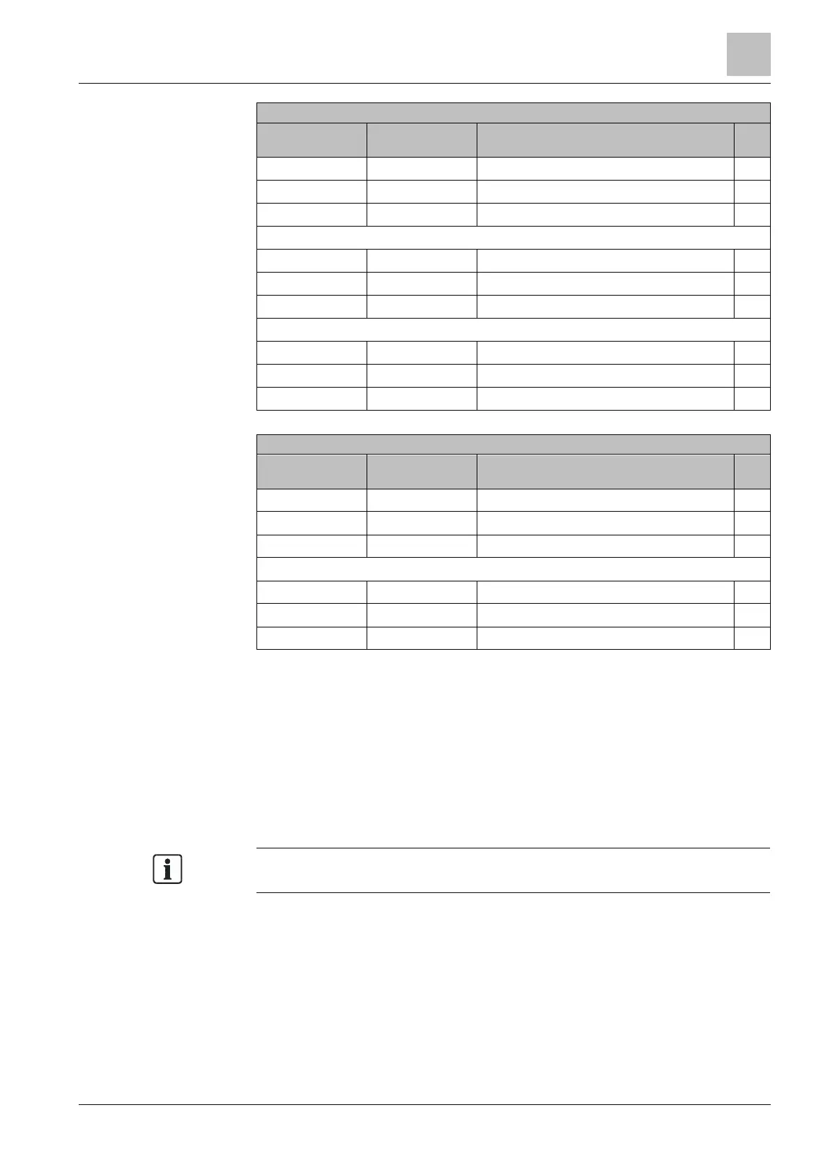
L1 DC- Diode block – OL/High impedance
L2 DC- Diode block – OL/High impedance
L3 DC- Diode block – OL/High impedance
DC + L1 Diode block – OL/High impedance
DC + L2 Diode block – OL/High impedance
DC + L3 Diode block – OL/High impedance
DC- L1 Diode aperture – typically 0.3 – 0.5V
DC- L2 Diode aperture – typically 0.3 – 0.5V
DC- L3 Diode aperture – typically 0.3 – 0.5V
U DC + Diode aperture – typically 0.3...0.5 V
V DC + Diode aperture – typically 0.3...0.5 V
W DC + Diode aperture – typically 0.3...0.5 V
U DC- Diode block – OL/High impedance
V DC- Diode block – OL/High impedance
W DC- Diode block – OL/High impedance
How to proceed if a fault is discovered
The variable speed drive has failed one of these tests:
Remove the Power Module (power unit) in order to replace or repair it.
A short circuit is present at the input rectifiers or at components of the IGBT
bridge:
Check the state of fuses in the supply line, of contactors, disconnectors or of
the motor itself.
Remember that an apparently open circuit can also occur following a component
short-circuit and the resulting strong flow of current.

 Loading...


