Service, maintenance and fault rectification
| 98
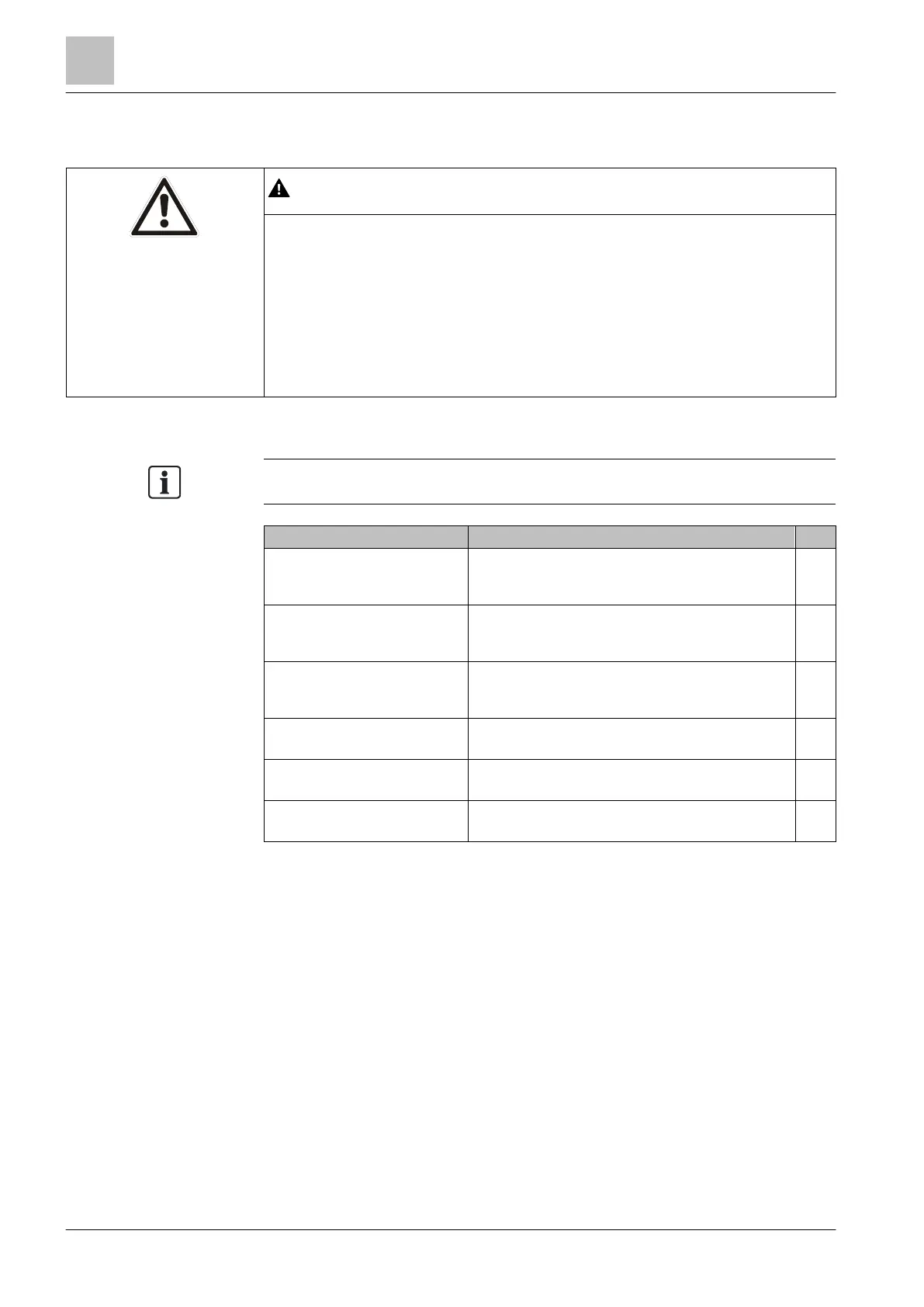
8.3.3.2 Power test
Danger due to electric current and moving parts during commissioning of
equipment or plant!
Components connected to the variable speed drive might move randomly while
the drive is being commissioned. Movements of this kind can cause serious
physical injury or death.
● Before commissioning the drive, make the system safe, for example by
cordoning it off.
● Ensure that all the covers are applied to the drive, and that no live parts are
Wherever possible, connect measuring equipment before switching the drive on.
Measuring DC bus voltage The measured DC voltage at the terminals (not available
on all types) should correspond to the peak-to-peak
voltage of the applied AC input (typically 580 V).
DC bus voltage – from parameter
r0070
r0070 is the measured DC bus voltage of the drive. This
does not function below 200 V DC. The parameter has
access level 3.
DC bus voltage – from parameter
r0026
r0026 is the measured, smoothed DC bus voltage of the
drive. This does not function below 200 V DC. The
parameter has access level 2.
Fan Check the incoming supply. If you can hear the
sounds of the fan, the incoming supply is okay.
10 V Check the incoming supply between terminals T35
and T36. 10 V are okay.
24 V Check the incoming supply between terminals T9
and T28. 24 V are okay.
How to proceed if a fault is discovered
The variable speed drive has passed all tests except the fan test:
Replace the fan as indicated in the Hardware Installation Manual.
If the fans are not working and the DC bus monitor shows 0, the Power Module
(power unit) may possibly be defective. The monitored DC bus signals indicate
that the microcontroller system for the drive is working properly. A problem in
the supply voltage could be the result of incorrect wiring. If the problem
persists:
Remove the wiring and carry out the test again
If the problem persists and the fan and the DC monitor are working properly,
the cause of the problem may reside in the Control Unit:
Check the Control Unit.

 Loading...


