System data
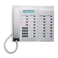
Euroset line 36/Hicom 118-2
A31003-K16-X001-3-7620
,
07/99
12-14
Hicom 100 E Version 2.1, Service manual
12.3.2 Hicom 118-2 motherboard
The MB 6/4 motherboard is the main board and accommodates 6 digital extension interfaces
(U
P0/E
), 4 analogue extension interfaces (a/b), the V.24 interface (SIC – serial interface cable),
the signalling unit (SIU), a real-time clock and a PCM highway controller and conference circuit.
Hicom 118-2 MB 6/4 - motherboard with 6 x U
P0/E
, 4 x a/b
An EXM or MPPI module can be connected to the appropriate MB for external music on hold.
The module also has a V.24 interface with a mini-DIN connector that can be used for outputting
or editing call charge data or customer data. Teleservice is possible via the V.24 interface.
U
P0/E
/ a/b extensions are connected by means of screw terminals. These terminals can be re-
moved from the module for installation or maintenance purposes, see Figure 12-8 or Figure 12-
9
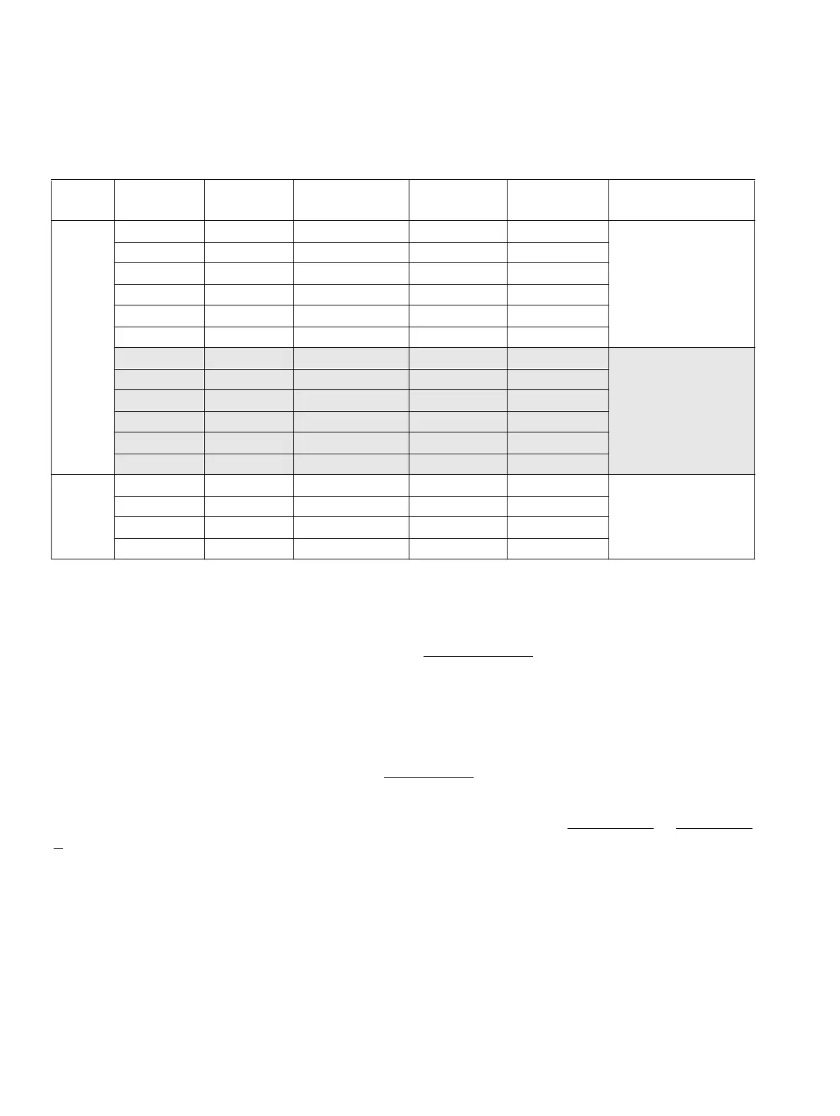
Hicom
118-2
Ext. no. Int. ext.
no.
DDI no. Port
numbering
Type
MB
U
P0/E
11 200 200 1 U
P0/E
MU
P0/E
master
12 201 201 2 U
P0/E
M
13 202 202 3 U
P0/E
M
14 203 203 4 U
P0/E
M
15 204 204 5 U
P0/E
M
16 205 205 6 U
P0/E
M
17 206 206 1 U
P0/E
S U
P0/E
slave
18 207 207 2 U
P0/E
S
19 208 208 3 U
P0/E
S
20 209 209 4 U
P0/E
S
21 210 210 5 U
P0/E
S
22 211 211 6 U
P0/E
S
a/b
23 212 212 1 a/b
24 213 213 2 a/b
25 214 214 3 a/b
26 215 215 4 a/b
Table 12-8 Standard numbering, MB 6/4 Hicom 118-2
 Loading...