Installing the system unit
Installation
A31003-K16-X001-3-7620
,
07/99
5-2
Hicom 100 E Version 2.1, Service manual
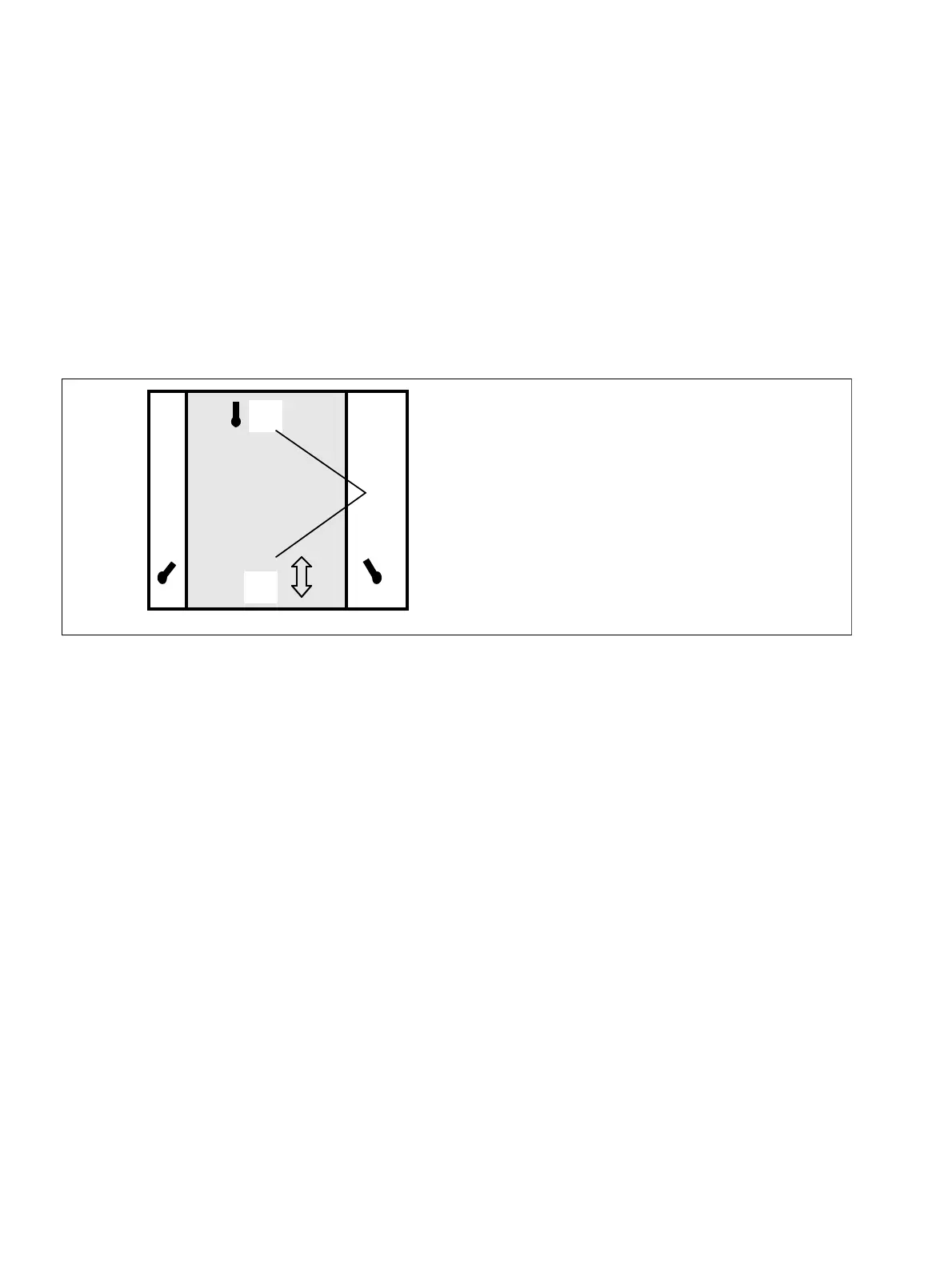
5.2 Installing the system unit
●
Drill hole, insert wall plug with screw supplied and turn screw until head projects by approx.
5 mm from surface of wall.
●
Engage screw (1) in hole at top of unit.
●
Mark positions of holes for remaining wall plugs (2) and remove unit.
●
Drill holes, insert wall plugs and turn screws until head projects by approx. 5 mm.
●
Engage unit on all three screws, align and tighten bottom screws.
Figure 5-2 Installing unit
5.3 Power supply
Power supply unit with PSU power cable (1.5 m) or UPS with power cable (1.5 m) and battery
adapter. Overall ratings:
●
PSU 1/UPS1 > 35W
●
PSU 2/UPS2 > 90W.
Mains input 230 Vac~
±
15% and 115 Vac~
±
15%. Input for 98 Vac to 264 Vac voltage range,
Frequency 50/60 Hz.
The ringing voltage is adjustable (in the GER version, permanently set to 75 Vac, not
adjustable):
●
75 Vac~
±
10% for 50 Hz or
●
75 Vac~
±
10% for 25 Hz
Insert and screw the PSU or UPS once the necessary add-on modules have been inserted.
(2)
(1)
Slots in
rear of housing
Unit
Basic box and
expansion box