Function expansions with options bus
Overview of modules
A31003-K16-X001-3-7620
,
07/99
3-22
Hicom 100 E Version 2.1, Service manual
3.6.3 Serial interface board (SIB) (V.24 connection)
An additional V.24 interface is offered as an optional babyboard in the GEE12/16 module hous-
ing. Level matching and galvanic isolation of the V.24 adapter are implemented on the SIB. The
2400 baud rate cannot be changed.
Up to 4 GEE modules can be installed; up to 4 serial interface boards can therefore be operat-
ed.
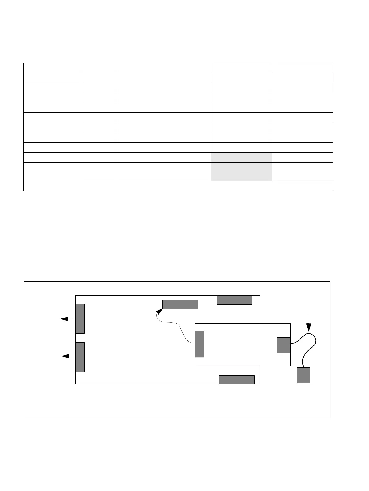
Figure 3-13 SIB (serial interface board) interfaces
Contact Port X3 Port X4 Port X5
1 a GND * Trunk 1 (AL1) 0V
2 b Trunk 1 (BN 1) Trunk 1 (BL1) 0V
3 a Trunk 1 (AN 1) Trunk 2 (AL2) RTS
4 b Trunk 2 (BN 2) Trunk 2 (BL2) CTS
5 a Trunk 2 (AN 2) Trunk 3 (AL3) RXD
6 b Trunk 3 (BN 3) Trunk 3 (BL3) TXD
7 a Trunk 3 (AN 3) Trunk 4 (AL4) 0V
8 b Trunk 4 (BN 4) Trunk 4 (BL4) +5V
9 a Trunk 4 (AN 4) 0V
10 Call charging module
assignment
+5V
* in the case of GEE 50 FRA (otherwise not assigned)
Table 3-19 Contact assignment of the GEE module
GEE module
X4
1
10
X3
1
8
to TLA
to trunk
MSI
X5
SIB
Connecting
2 sub-D plugs
(9-pin)
MB side
Module side
Connecting cable
to printer/PC
cable