programmed. When determining the end point, a distinction is made between the following
three cases:
1. No geometry axis is programmed in the SAR block. In this case, the contour ends at point P
1
(if DISRP has been programmed), at point P
2
(if DISCL, but not DISRP has been
programmed) or point P
3
(if neither DICLS nor DISRP has been programmed).
The position in the axes, which describe the machining plane, is determined by the
retraction contour (end point of the straight line or arc). The axis component perpendicular
to this is defined by DISCL or DISPR. If in this case both DISCL=0 and DISRP=0, the motion
is completely in the plane, i.e. points P
0
to P
3
coincide.
2. Only the axis perpendicular to the machining plane is programmed in the SAR block. In this
case, the contour ends at point P
0
. If DISRP has been programmed (i.e. points P
0
and P
1
do
not coincide), the straight line P
1
→ P
0
is perpendicular to the machining plane. The positions
of the two other axes are determined in the same way as in 1.
3. At least one axis of the machining plane is programmed. The second axis of the machining
plane can be determined modally from its last position in the preceding block.
The position of the axis perpendicular to the machining plane is generated as described in 1.
or 2., depending on whether this axis is programmed or not. The position generated in this way
defines the end point P
0
. If the SAR retraction block is also used to deactivate the tool radius
compensation, in the first two cases, an additional path component is inserted in the machining
plane from P
1
to P
0
so that no movement is produced when the tool radius compensation is
deactivated at the end of the retraction contour, i.e. this point defines the tool center point and
not a position on a contour to be corrected. In case 3, no special measures are required for
deselection of the tool radius compensation, because the programmed point P
0
already directly
defines the position of the tool center point at the end of the complete contour.
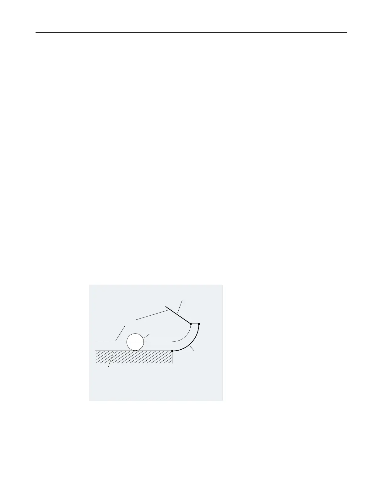
The behavior in cases 1 and 2, i.e. when an end point is not explicitly programmed in the
machining plane with simultaneous deselection of the tool radius compensation, is shown in the
following figure:
&RQWRXUSUHYLRXVEORFN
7RRO
7RROFHQWHUSRLQWSDWK
)ROORZLQJEORFNZLWKRXWFRPSHQVDWLRQ
:$%EORFN
**
$WWUDFWLRQZLWK:$%DQGVLPXOWDQHRXV
GHDFWLYDWLRQRIWKHWRROUDGLXVFRPSHQVDWLRQ
3
3
3
Fundamentals
2.10 Tool radius compensation
NC programming
Programming Manual, 12/2019, 6FC5398-2EP40-0BA0 279
 Loading...


