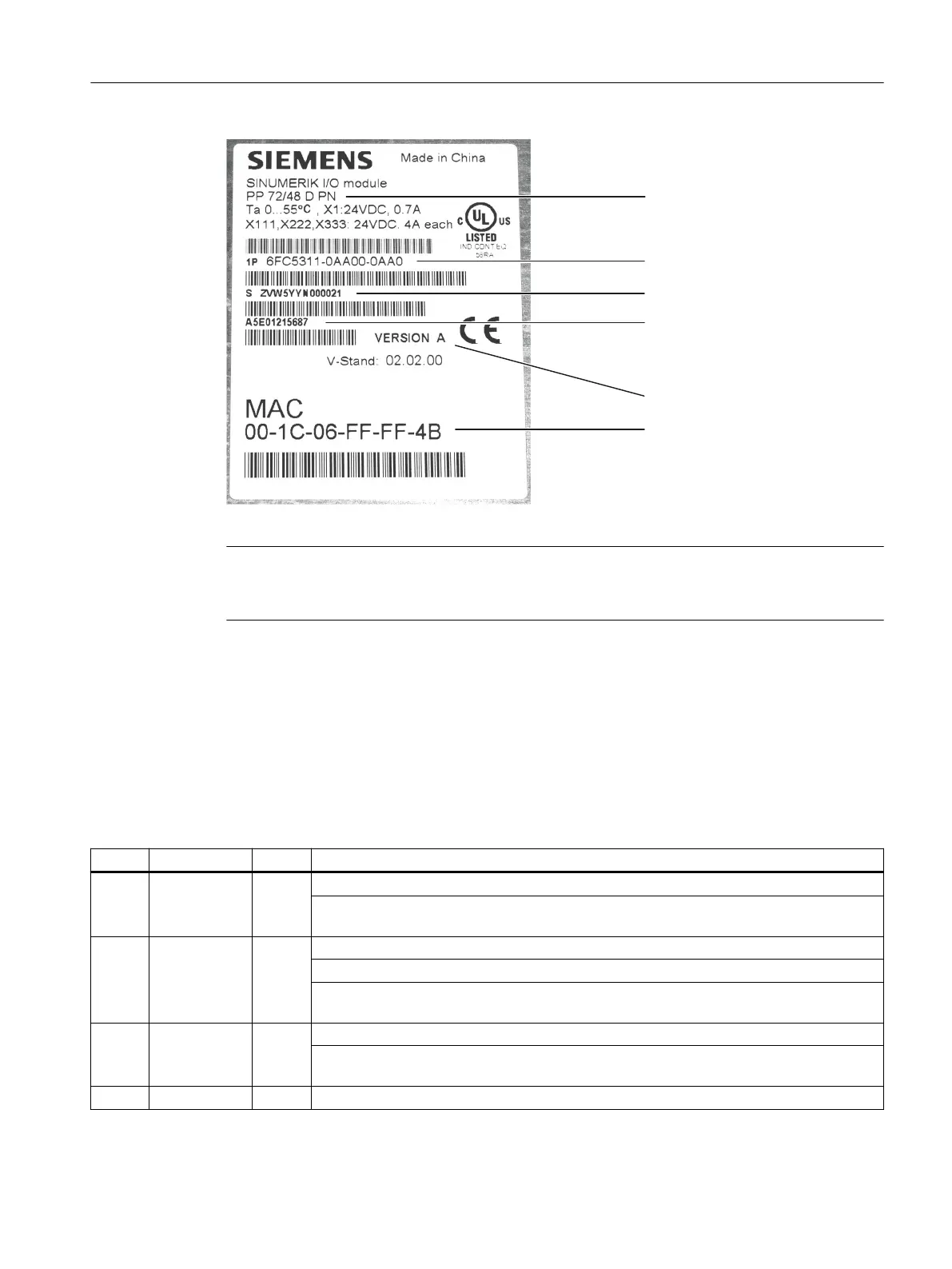
2UGHUQXPEHU
6HULDOQXPEHU
0DWHULDOQXPEHU
0$&DGGUHVV
+:YHUVLRQ
&RPSRQHQWQDPH
Figure 9-8 PP 72/48D PN type plate
Note
The type plate is located on the rear side of the mounting plate. It is advisable to make a note of
relevant data as it is no longer visible after installation.
LED displays
Each PROFINET port has two integrated LEDs displaying the link status (green) and activity
(orange); see chapter Application (Page 60).
The PP 72/48 D PN has the following additional LEDs, which provide information on the module
status:
Table 9-11 LEDs: Status display
Name Designation Color Description
H1 PowerOK Green Lit: Power supply ok
O: As soon as one of the generated logic voltages falls below its setpoint, a reset is
triggered and the PowerOK LED goes out.
H2 PNSync Green Lit: Task system is synchronized to the bus cycle clock.
O: Task system is not synchronized to the bus cycle clock.
Flashes 0.5 Hz: Task system has synchronized to the bus cycle clock and cyclic data ex‐
change is running.
H3 PNFault Red O: Module is operating without error.
Lit: A system error has occurred (faulty module, incorrect parameterization by the PROFI‐
NET controller, etc. ).
H4 DIAG1 Green Reserved
Connectable components
9.2 PP 72/48D PN
NCU 7x0.3B PN
Equipment Manual, 10/2020, 6FC5397-1EP40-6BA1 101
 Loading...


