3.4.5 Start-up and mode selector switch
Layout
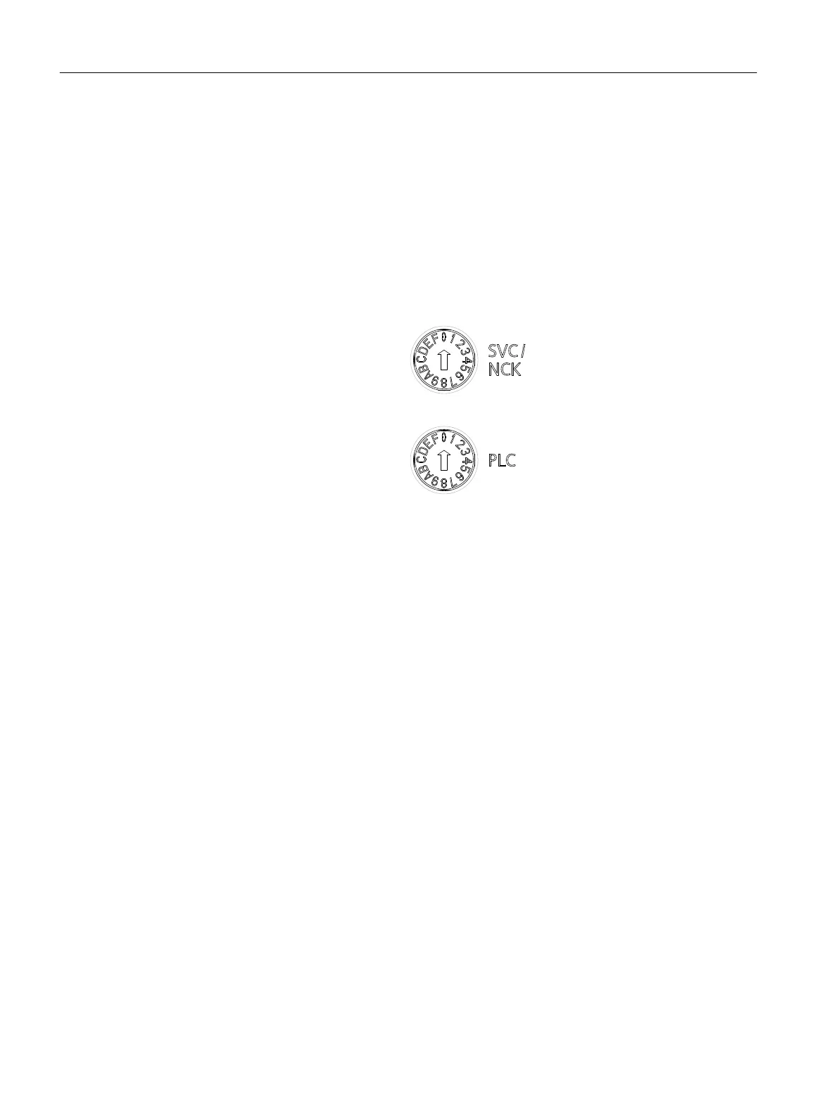
The NCU has two coding rotary switches in the lower section of the front panel:
• The upper switch (labeled SVC/NCK) is the NCK commissioning switch.
Setting during normal operation: "0"
• The lower switch (labeled PLC) is the PLC mode selector switch.
Setting during normal operation: "0"
3/&PRGHVHOHFWRUVZLWFK
1&.FRPPLVVLRQLQJVZLWFK
Figure 3-5 Startup and mode selector switch
Additional references
CNC Commissioning Manual Part 1 (NCK, PLC, drive)
3.5 Dual fan/battery module
Functions of the dual fan/battery module
The dual fan/battery module has the following tasks:
• Cooling the CPU by means of two redundant fans.
• Buering of the real time clock.
The temperature inside the NCU and the correct functioning of the fan are monitored. Fan faults
are displayed and can be read out by means of the diagnostic buer.
• Fan alarm ⇒ alarm 2110 "NCK temperature alarm": if one of the two fans no longer rotates
or the speed is out of tolerance.
• Fan fault ⇒ alarm 2120 "NCK fan alarm type %1": if none of the fans rotate.
If the software does not respond within approx. 1 minute, the components are shut down
automatically and the status is indicated by means of the red SF LED.
You can nd more information on the alarms in the Diagnostics Manual.
Description
3.5 Dual fan/battery module
NCU 7x0.3B PN
30 Equipment Manual, 10/2020, 6FC5397-1EP40-6BA1
 Loading...


