Wiring the bus connector
1. Proceed as follows to connect the bus connector:
2. Plug the bus connector into the corresponding interface on the NCU.
3. Screw the bus connector into place.
As the NCU is located at the start or end of a segment, you must switch on the terminating
resistor ("ON" switch setting).
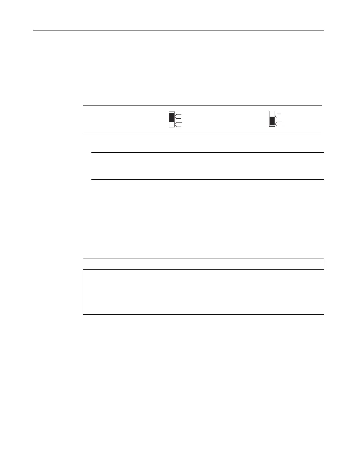
7HUPLQDWLQJUHVLVWRU
VZLWFKHGRQ
7HUPLQDWLQJUHVLVWRU
VZLWFKHGRII
RQ
RII
RQ
RII
Figure 7-10 Terminating resistor switched on and o
Note
Make sure that the stations on which the terminating resistor is located are always supplied
with voltage during booting and operation.
7.9.6 Disconnecting stations from the PROFIBUS
Removing the bus connector
You can remove the bus connector with a looped-through bus cable from the PROFIBUS DP
interface at any time without interrupting data trac on the bus.
NOTICE
Data exchange on the bus can be interrupted!
A bus segment must always be terminated with the terminating resistor at both ends. This is
not the case, for example, if the last node with a bus connector is de-energized. Because the bus
connector takes its voltage from the node, this terminating resistor is ineective.
Make sure that the nodes at which the terminating resistor is connected are always energized.
7.9.7 Operating the X136 interface as MPI
Applications
The X136 interface can also be operated as an MPI interface instead of a PROFIBUS DP interface.
187.5 kbit/s is the typical (preset) data rate. A maximum data rate of 12 Mbit/s can be set to
communicate with other CPUs. However, it should be noted that the maximum data rate is not
supported by all CPUs (e.g. smaller SIMATIC S7 CPUs).
Connecting
7.9 PROFIBUS DP
NCU 7x0.3B PN
Equipment Manual, 10/2020, 6FC5397-1EP40-6BA1 71
 Loading...


