7.10.2 Block diagram
Block diagram
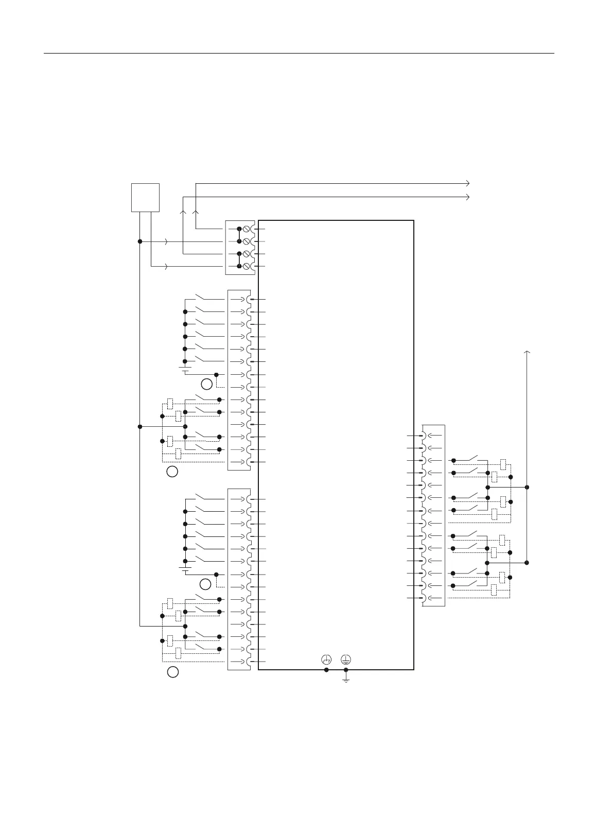
The following diagram shows the block diagram for the digital inputs/outputs of an NCU.
H[W
9
H[W
9
5HVHUYHG
5HVHUYHG
1&8[%31
0
0
9
0
0
','2
','2
','2
','2
0
0
',
',
',
',
0
0
','2
','2
','2
0
0
',
',
',
',
','2
0
;
0
;
;
0
0
',
',
',
',
0
0
0
,1287
,1287
0
,1287
,1287
,1287
,1287
,1287
,1287
;
① Jumper open: Isolation for digital inputs
② can be parameterized as digital input/output
Figure 7-12 Block diagram for digital inputs/outputs
Connecting
7.10 Digital inputs/outputs
NCU 7x0.3B PN
78 Equipment Manual, 10/2020, 6FC5397-1EP40-6BA1
 Loading...


