Signal type Meaning
V Supply voltage
GND Protective ground (reference potential)
Note
Digital and analog signals must not be laid together within a cable.
9.3.4.2 X1 power supply
Properties
This interface is intended exclusively for the connection of the external 24 V power supply.
On the module side, the power supplies are protected against:
• Polarity reversal
• Short-circuit (elec. current limitation of the outputs)
• Overload (self-restoring PTC fuse - Multifuse)
Requirements placed on the DC power supply
WARNING
Inadequately fused supply cables can be life-threatening
In the case of supply lines > 10 m, protectors must be installed at the device input in order to
protect against lightning (surge).
The DC power supply must be connected to the ground/shield of the I/O module for EMC and/
or functional reasons. For EMC reasons, this connection should only be made at one point; see
also EMC Installation Guide.
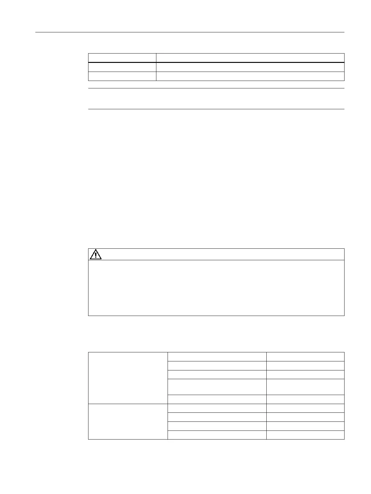
Table 9-34 Requirements of the DC power supply
Rated voltage According to EN 61131-2 24 V DC
Voltage range (average value) 20.4 V DC to 28.8 V DC
Voltage range (dynamic) 18.5 to 30.2 V DC
Voltage ripple peak-to-peak 5% (unltered 6-pulse recti‐
cation)
Booting time at POWER ON Any
Non-periodic overvoltages ≤ 35 V
Duration of overvoltage ≤ 500 ms
Recovery time ≥ 50 s
Events per hour ≤ 10
Connectable components
9.3 PP 72/48D 2/2A PN
NCU 7x0.3B PN
Equipment Manual, 10/2020, 6FC5397-1EP40-6BA1 123
 Loading...


