Using shielded cables
When using a shielded cable for the bidirectional inputs/outputs, the following options are
available for the shield connection:
1. Attach the cable shield to a grounded shielding bus immediately after the cable entry point
in the cabinet (strip the insulation o the cable for this purpose).
2. Continue routing the shielded cable as far as the module but do not make a connection to the
shield there.
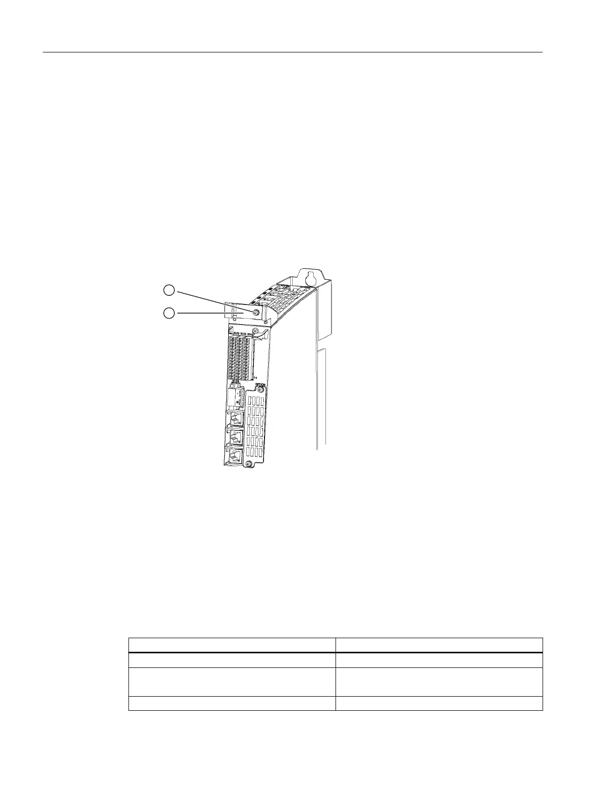
Using a shield connection
1. Remove the xing bracket of the shield connection.
2. Insert the cable and fasten the xing bracket.
① Fixing bracket of the shield connection
② Torx screw M3/0.8 Nm
Figure 7-13 Shield support
7.10.4 Technical data
Digital inputs on X122/X132
Table 7-29 Technical data of digital inputs X122/X132
Parameters Values
Voltage -3 V to +30 V DC
Typical current consumption 9 mA at 24 V DC (only with NCU 710.3B)
2.5 mA at 24 V DC (only with NCU 720.3B/ 730.3B)
Galvanic isolation Reference potential is terminal G1 or G2
Connecting
7.10 Digital inputs/outputs
NCU 7x0.3B PN
80 Equipment Manual, 10/2020, 6FC5397-1EP40-6BA1
 Loading...


