Value
byte 1
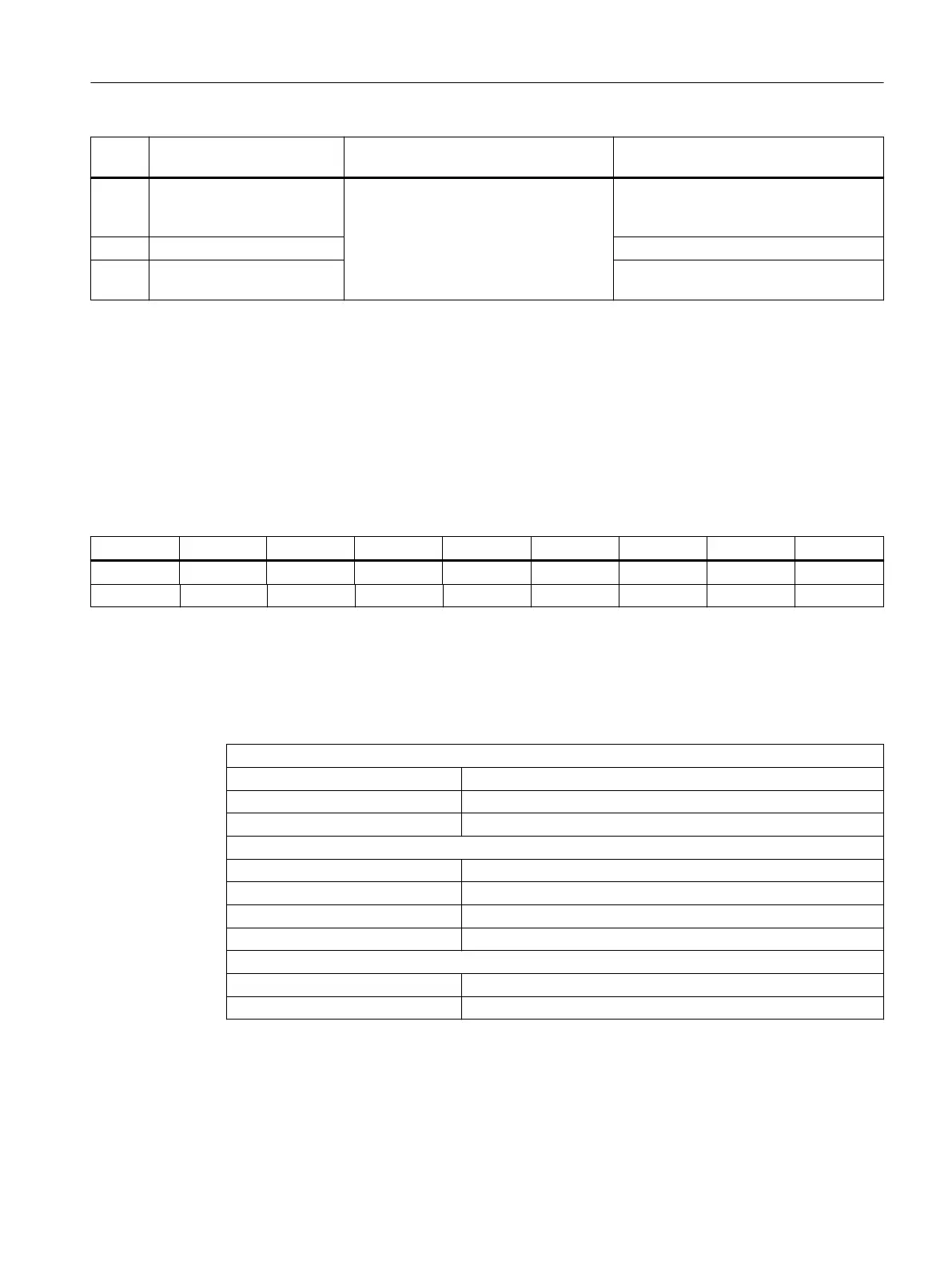
Cause Eect Remedy
5 Internal error, system error The "PNFault" LED is activated.
The outputs are disabled.
1)
The value 0x80 is stored in status byte 1.
The rmware has detected a system error,
this status can only be exited by means of
a switch-on / switch-o.
6 Range exceeded at the inputs Check input circuit and adjust, if required.
7 Range exceeded at the out‐
puts
Correct the values in the user program.
1)
The analog outputs retain their last specied value.
Diagnostics via status bytes 0/1
In status byte 0, the set operating modes are reected e.g. "0x55" if control byte 0 = 0x55 has
been specied (voltage on all channels).
In the event of an error, the error bit is set in status byte 1 (bit 7). In the event of an error in one
channel, all channels are deactivated.
Table 9-66 Input image of analog inputs (excerpt)
Byte Bit7 Bit6 Bit5 Bit4 Bit3 Bit3 Bit1 Bit0
m+0 0 0 0 0 0 0 0 0
m+1 Error bit 0 0 0 0 0 0 0
9.3.6 Technical data
Table 9-67 Technical data of the I/O module
Safety
Degree of protection IP 00 according to EN 60529
Protection class III; DVC A, (PELV) acc. to EN 61800-5-1
Approvals cULus, CE
Electrical data
Rated voltage 24 V DC
Rated current 0.7 A
Power consumption at rated load 19 W (without digital outputs)
Power loss 18 W
Mechanical data
Dimensions WxHxD 150 x 300 x 35 mm
Weight, approx. 0.9 kg
For detailed technical data relating to the inputs and outputs, see the "Connecting" chapter.
X111, X222 and X333 digital inputs/outputs (Page 128)
Analog X3 inputs/outputs (Page 133)
Connectable components
9.3 PP 72/48D 2/2A PN
NCU 7x0.3B PN
Equipment Manual, 10/2020, 6FC5397-1EP40-6BA1 145
 Loading...


