Checkback signal of the operating modes
The set operating modes are saved in the input image in Status Byte 0. This value must be
compared with Control Byte 0 in the output image. If these are dierent, an error has occurred,
e.g. in the case of overvoltage in the "Temperature measurement" operating mode,
see Diagnostics via input image (Page 143).
9.3.5.3 Analog value representation
Note
The analog values of the inputs and outputs are written or read in 16 bit data format i.e. they
must be accessed word by word.
The analog values are provided as 16 bit integer values. Depending on the operating mode, the
measured values must be converted using the following factors in order to achieve the
corresponding physical value.
Voltage [V] Current [mA] Temperature [°C]
Factor (AI): 0.00152 0.00305 0.1
Factor (AO): 0.00038 0.00076 -
Calculation: 16 bit value (hex. or dec.) * factor = measured value
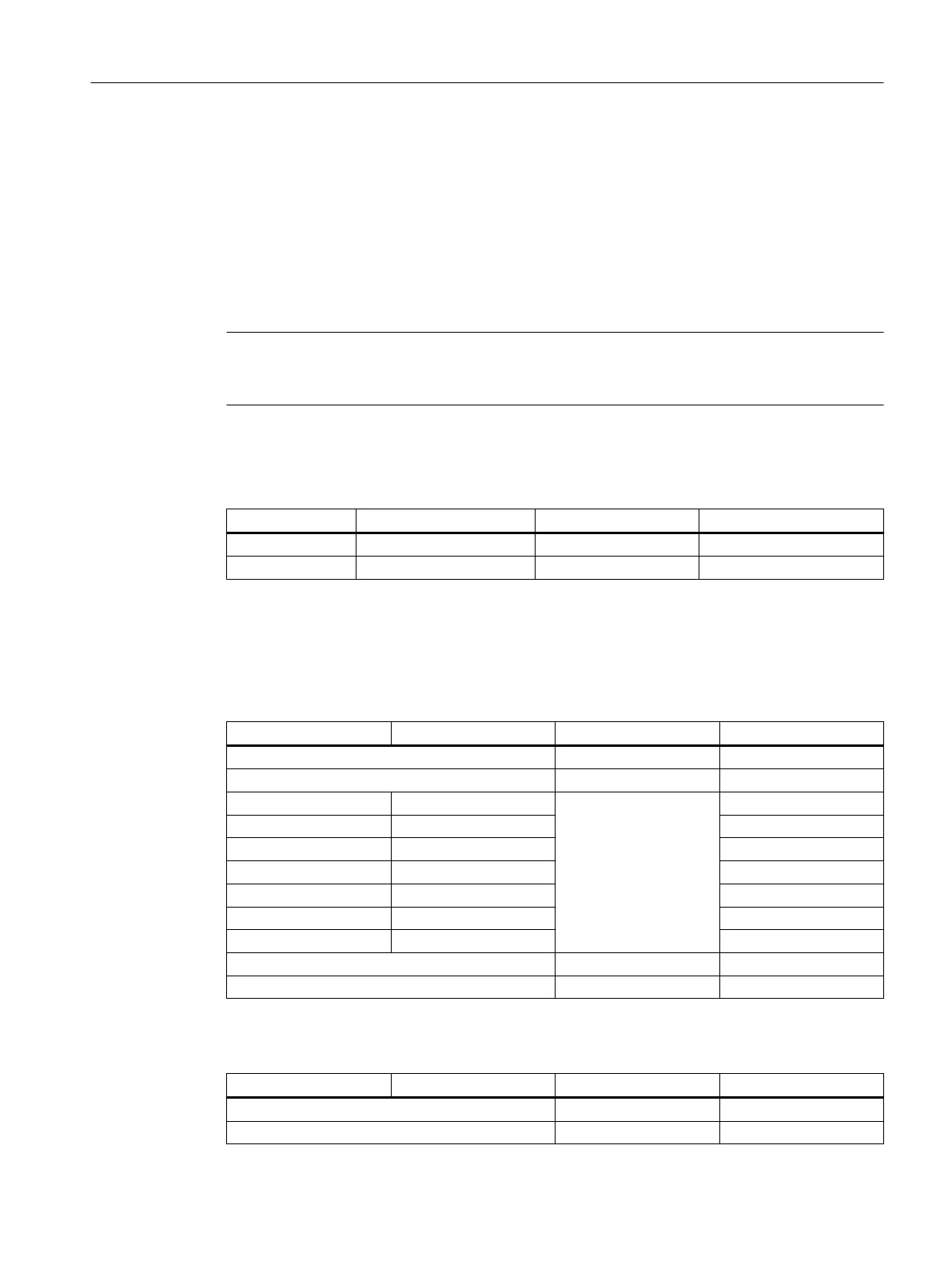
Analog inputs
Table 9-57 Measured values in the voltage measurement operating mode
16 bit value (hex.) 16 bit value (dec.) Factor Voltage value [V]
Overow - Deactivation
Overrange - Up to 11.75 V
0x19B5 6581
0.00152
10 V
0x0CDA 3291 5 V
0x066D 1645 2.5 V
0x0000 0 0 V
0xF993 -1645 -2.5 V
0xF326 -3291 -5 V
0xE64B -6581 -10 V
Underrange - Up to -11.75 V
Underow - Deactivation
Table 9-58 Measured values in the current measurement operating mode
16 bit value (hex.) 16 bit value (dec.) Factor Current value [V]
Overow - Deactivation
Overrange - Up to 23.5 mA
Connectable components
9.3 PP 72/48D 2/2A PN
NCU 7x0.3B PN
Equipment Manual, 10/2020, 6FC5397-1EP40-6BA1 141
 Loading...


