Note
The fast digital inputs/outputs must be shielded.
7.10.3 Connecting digital inputs/outputs
Cable specication
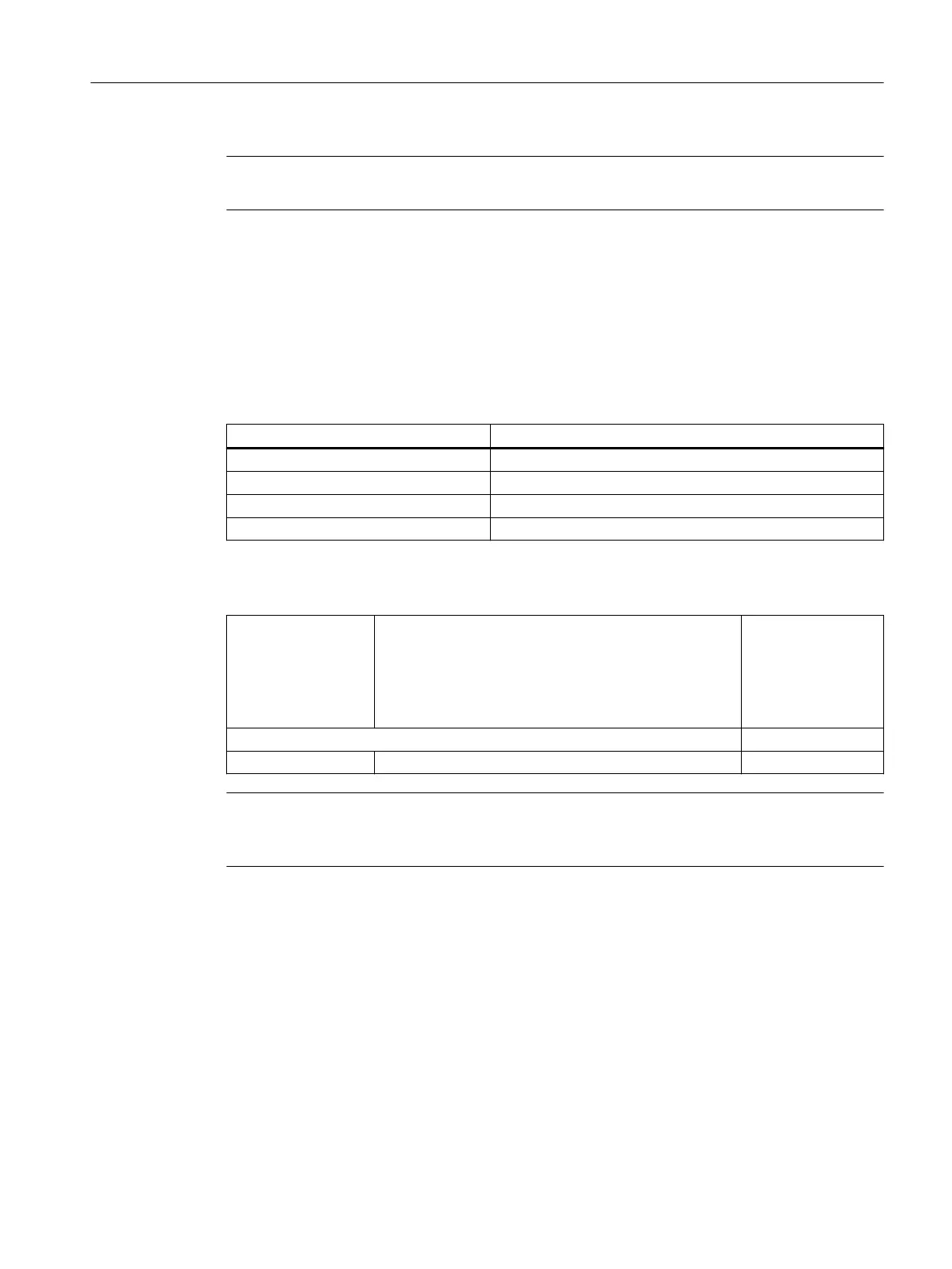
Table 7-27 Cable specication at X122 / X132 / X142
Features Version
Connector type 14-pin spring-loaded terminals
Connection option 0.2 to 1.5 mm
2
Max. current carrying capacity 6 A
Max. cable length 30 m
Table 7-28 Connectable conductor cross-sections
Connectable conduc‐
tor cross-sections
Rigid
Flexible
Flexible, with end sleeve without plastic sleeve
Flexible, with end sleeve with plastic sleeve
AWG / kcmil
0.2 to 1.5 mm
2
0.2 to 1.5 mm
2
0.25 to 1.5 mm
2
0.25 to 0.75 mm
2
24 to 16
Stripped length 10 mm
Tool Screwdriver 0.4 x 2.0 mm
Note
To achieve optimum interference suppression, shielded cables must be used to connect
measuring inputs or BEROs.
Wiring digital inputs/outputs
1. Strip 10 mm of insulation from the wires.
2. Wire the digital inputs of the interface for connection of the sensors.
3. Wire the digital outputs of the interface for connection of the actuators.
4. Insert the cable into the corresponding spring-loaded terminal.
Connecting
7.10 Digital inputs/outputs
NCU 7x0.3B PN
Equipment Manual, 10/2020, 6FC5397-1EP40-6BA1 79
 Loading...


