Maximum current consumption: 3 x 4 A if all outputs are used simultaneously.
Note
It is the user's responsibility to ensure that the max. current consumption per DOCOMx pin
(X111, X222, X333: Pins 47, 48, 49, 50) does not exceed 1 A. The power supply (+24 V DC) for
the digital outputs must therefore be connected to all 4 pins per DOCOMx (X111, X222, X333:
pins 47, 48, 49, 50).
Wiring the power supply
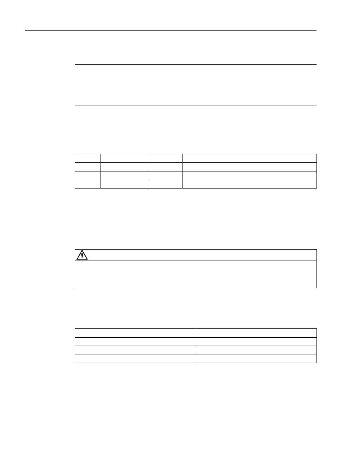
Table 9-14 Pin assignment at X1 screw-type terminal block
Pin Signal name Signal type Meaning
1 P24 VI 24 V DC power supply
2 M GND Ground
3 PE GND Protective ground
Current requirement
0.7 A (at 24 V DC) for PP 72/48D PN and digital inputs plus 3 x 4 A at X111, X222 and X333 for
supplying digital outputs.
Wiring the screw-type terminal block
The required 24 V DC load power supply is wired to the screw-type terminal block (X1).
DANGER
Danger of death caused by unsafe power supply
The 24 V direct voltage is to be congured as an extra-low voltage with protective separation
- DVC A or PELV according to EN 61800-5-1.
Power cables
Table 9-15 Cable specication at X1
Characteristics Version
Connection option Up to 2.5 mm
2
Current carrying capacity max. 10 A
Max. cable length 10 m
Use exible cables with a cross-section of 0.25 to 2.5 mm
2
(or AWG 23 to AWG 13) for wiring the
power supply according to the maximum current that ows.
If you only use one wire per connection, an end sleeve is not required.
You can use end sleeves without an insulating collar in accordance with DIN 46228, Form A long
version.
Connectable components
9.2 PP 72/48D PN
NCU 7x0.3B PN
106 Equipment Manual, 10/2020, 6FC5397-1EP40-6BA1
 Loading...


