Pin Signal name Signal type Meaning
5 N.C. - Reserved, do not use
6 RX- I Receive data -
7 N.C. - Reserved, do not use
8 N.C. - Reserved, do not use
Cable specication
Table 9-38 Cable specication at X2, ports 1, 2
Characteristic Version
Connector type RJ45 socket
Cable type Industrial Ethernet cable (CAT5)
Max. cable length 100 m
LED displays
For diagnostic purposes, the RJ45 sockets are each equipped with a green and a yellow LED. This
allows the following information to be displayed for the respective PROFINET port:
Table 9-39 PROFINET ports LED displays
Name Color Status Meaning
Link Green lit Transfer rate 100 Mbit/s
o No or faulty connection
Activity Orange lit Data exchange
o No data exchange
PROFINET address (S1)
A logical address can be assigned to the I/O module for communication with PROFINET using a
10-bit DIP switch S1.
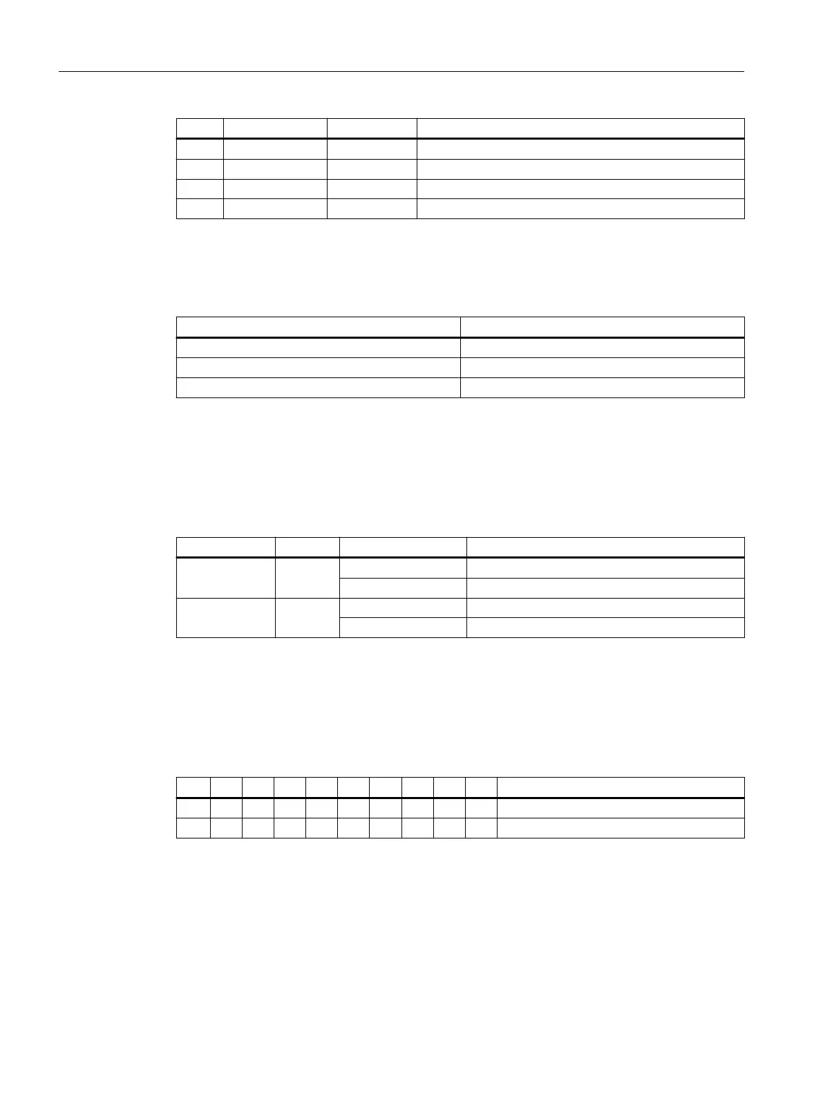
Table 9-40 General settings with switch S1
1 2 3 4 5 6 7 8 9 10 Meaning
on on PROFINET functionality
on on on on on on on on DCP mode
The switch positions 9 and 10 guarantee the PROFINET functionality of the module and must
always be switched "on".
DCP mode
In this mode, there is no default device name.
The device name must be set using initialization and remains saved on the I/O module. It is rst
deleted when the factory setting is restored, e.g. using STEP7.
Connectable components
9.3 PP 72/48D 2/2A PN
NCU 7x0.3B PN
126 Equipment Manual, 10/2020, 6FC5397-1EP40-6BA1
 Loading...


