Digital inputs
• Characteristics:
– X222: DI 3.0 to 3.7 are connected as rapid inputs.
– The inputs have no signaling (status LEDs).
– The inputs are not isolated.
– It is not possible to connect 2-wire BEROs.
• Terminal assignment for the digital inputs:
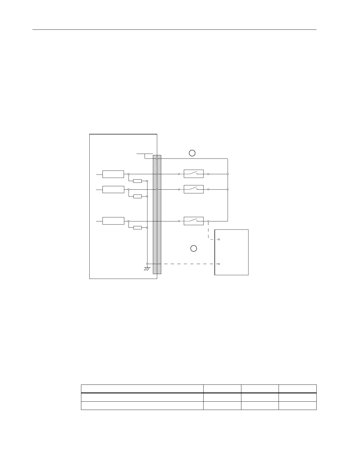
The following gure shows an example of the terminal assignment for the digital inputs on
connector X111. Connectors X222 and X333 are assigned analogously.
3LQQXPEHU
5HFHLYHU
([WSRZHUVXSSO\
3287H[W
VWDELOL]HG
5HFHLYHU
5HFHLYHU
33'$31
;;;
3287
9'&
0
9
9
① when using the internal power supply P24OUT
② when using the external power supply P24OUT
ext
Figure 9-17 Terminal assignment for the digital inputs
• Power supply for digital inputs (X111, X222, X333: Pin 2)
– The internal power supply (P24OUT) is taken from the general power supply of module
X1, pin 2 (P24).
– Alternatively, an external power supply can be connected if the load at the digital outputs
becomes too high.
• Technical data:
Table 9-45 Electrical specication of the digital inputs:
Digital inputs min. max. Nominal
High-level voltage (U
H
) 15 V 30 V 24 V
Input current I
IN
at V
H
2 mA 15 mA -
Connectable components
9.3 PP 72/48D 2/2A PN
NCU 7x0.3B PN
Equipment Manual, 10/2020, 6FC5397-1EP40-6BA1 131
 Loading...


