X3 pin assignment
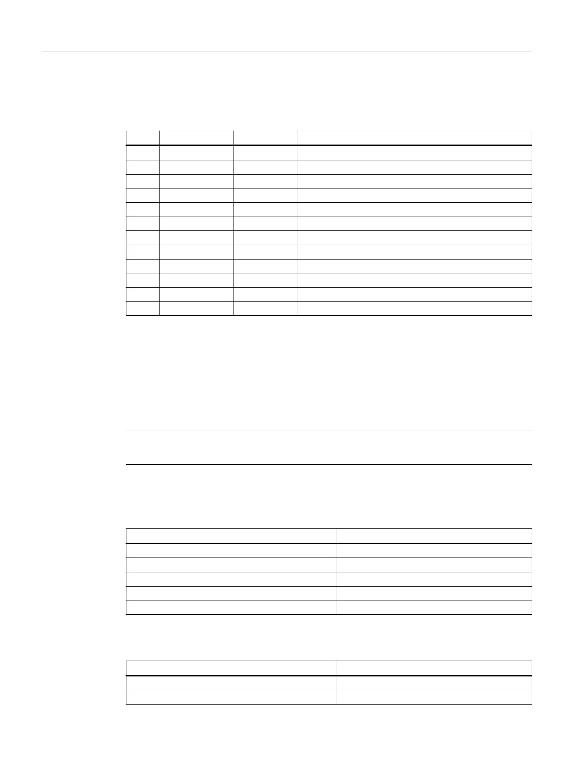
Table 9-47 Pin assignment (standard)
Pin Signal name Signal type Meaning
1 CO1 O Channel 1 current output for PT100
2 CI1 I Channel 1 current input for PT100
3 AI1+ I Channel 1 analog input +
4 AI1- I Channel 1 analog input -
5 CO2 O Channel 2 current output for PT10
6 CI2 I Channel 2 current input for PT100
7 AI2+ I Channel 2 analog input +
8 AI2- I Channel 2 analog input -
9 AO3+ O Channel 3 current and voltage output +
10 AO3- O Channel 3 current and voltage output -
11 AO4+ O Channel 4 current and voltage output +
12 AO4- O Channel 4 current and voltage output -
The analog signal to be measured is connected to the terminals AI 1+/- and AI 2+/-. AI stands for "Analog
Input". The CO "Current Output" and CI "Current Input" terminals supply the constant current for the 4-wire
measurement of PT100 elements.
Analog inputs
The module has two analog inputs. These can optionally be assigned parameters as voltage,
current or PT100 input.
Note
The analog inputs are only enabled following the parameter assignment.
Cycle time of the analog value accumulation: 20 ms per channel
Table 9-48 Technical specications in the "voltage input" operating mode
Parameter Value
Input range (rated value) - 10 V to + 10 V
permitted overrange - 11.75 V to + 11.75 V
Resolution 16 bits (including sign)
Accuracy +/- 0,5 %
Internal resistance Ri 100 KOhm
Table 9-49 Technical specications in the "current input" operating mode
Parameter Value
Input range (rated value) - 20 mA to + 20 mA
Permitted overrange - 23.5 mA to + 23.5 mA
Connectable components
9.3 PP 72/48D 2/2A PN
NCU 7x0.3B PN
134 Equipment Manual, 10/2020, 6FC5397-1EP40-6BA1
 Loading...


