6LJQDOQDPH
%XV
;
,
F
$'8
&,[
&2[
33'$31
$,[
$,[
x 1, 2
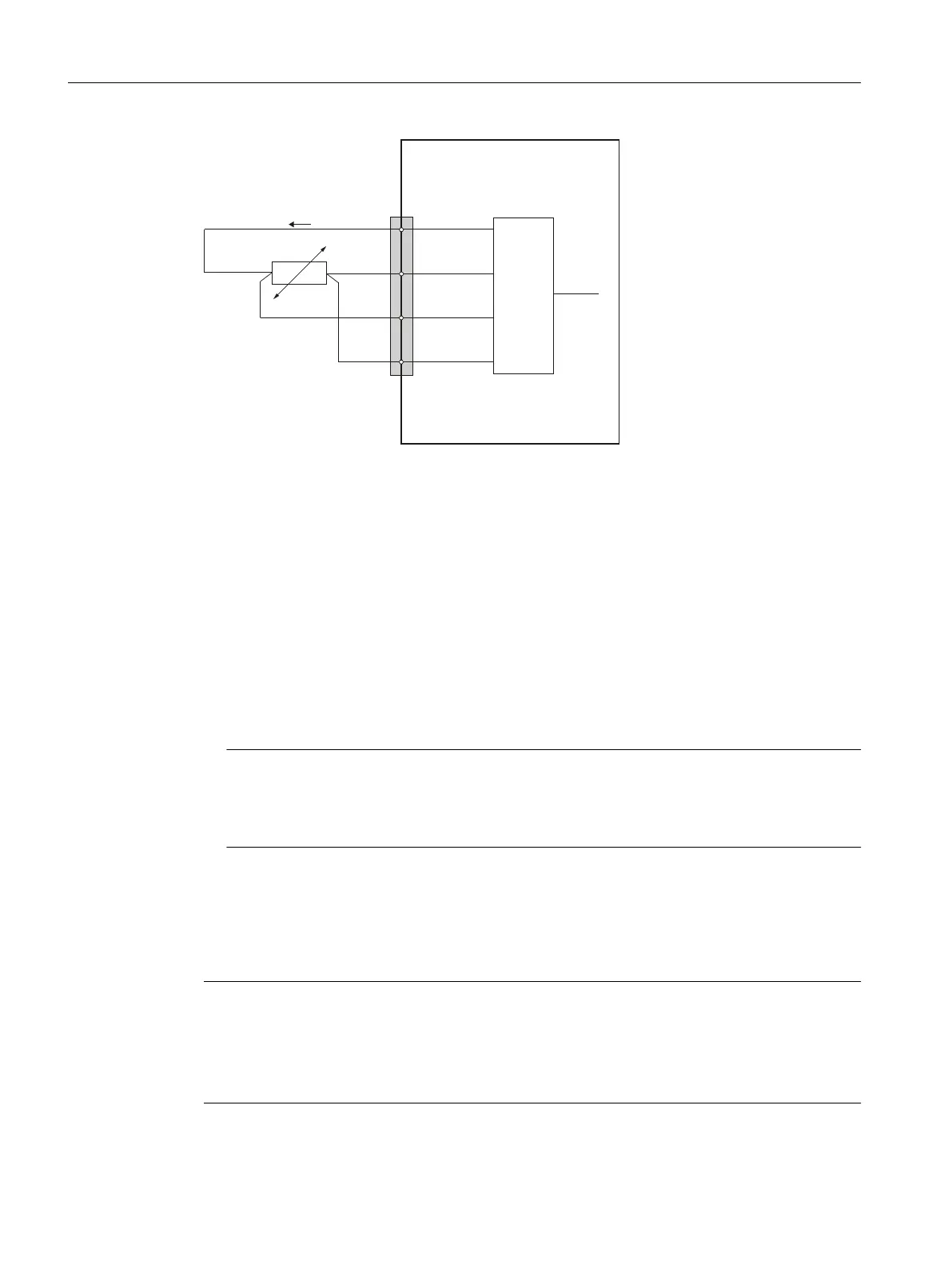
ADU Analog Digital Unit
I
c
Constant current
Figure 9-19 PT100 pin assignment
Measurement using a 3-wire connection system
The following pins must be jumpered at connector X3 in order to perform the measurement in
the PT100 using a 3-wire connection system:
• Temperature measurement with channel 1:
Short-circuit pin 2 (CI 1) and pin 4 (AI 1-) and connect the jumper at connector X3
• Temperature measurement with channel 2:
Short-circuit pin 6 (CI 2) and pin 8 (AI 2-) and connect the jumper at connector X3.
Note
Measuring accuracy
The accuracy of the temperature input becomes poorer: The resistance of the connecting
cable of the jumpered connecting cable falsies the measurement.
Analog outputs
The module has two analog outputs. These can optionally be assigned parameters as voltage or
current output.
Note
The analog outputs are only enabled following the parameter assignment.
From the switch-on of the I/O module to when it is enabled, the analog outputs do not read 0 V,
but are dened by a voltage pulse at -0.2 V. This value must be taken into consideration when
specifying the setpoint value.
Connectable components
9.3 PP 72/48D 2/2A PN
NCU 7x0.3B PN
136 Equipment Manual, 10/2020, 6FC5397-1EP40-6BA1
 Loading...


