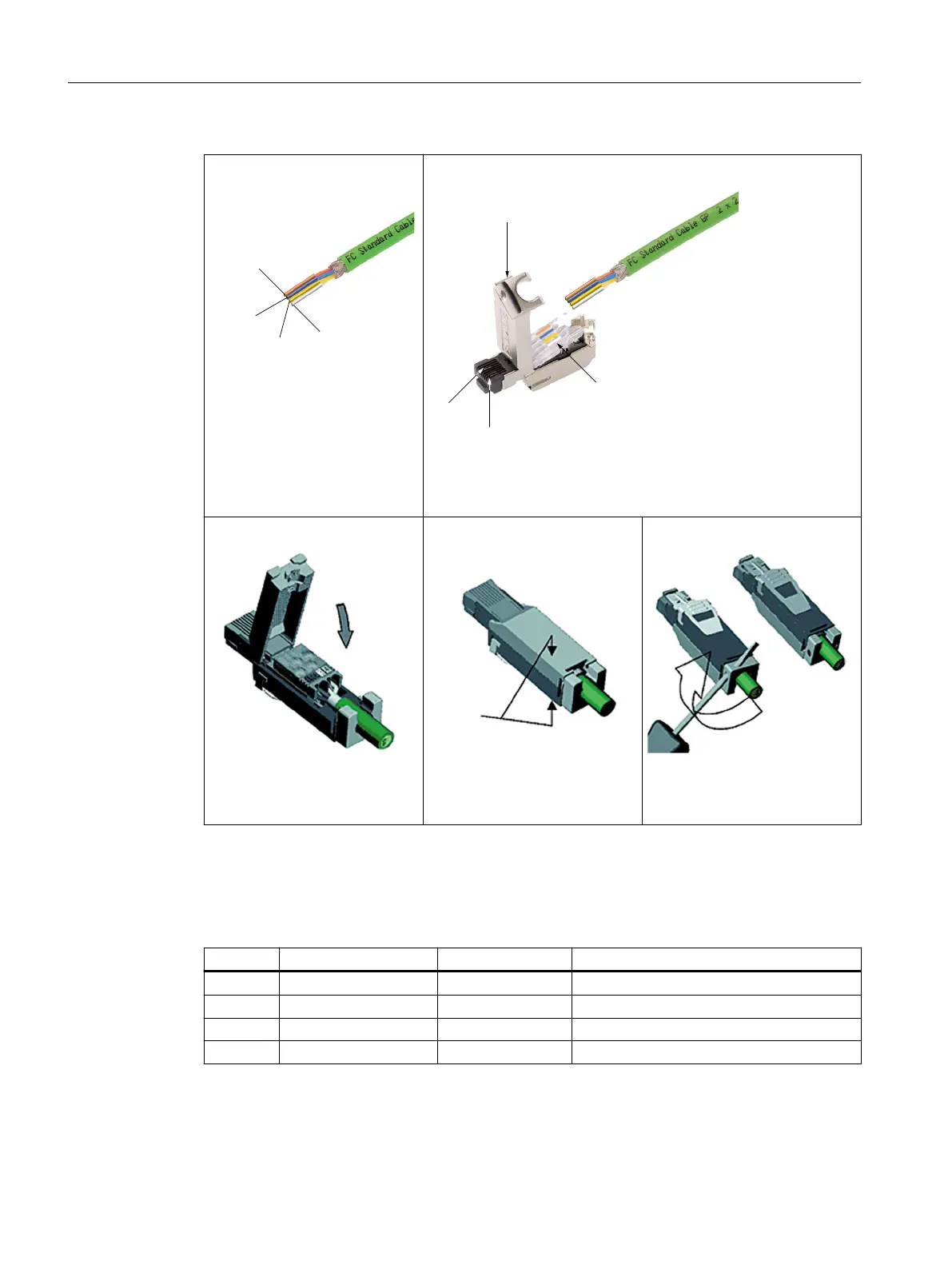
①
Strip the IE FC Cable 2x2 using a
stripping tool and separate out
the cores according to the color
coding on the contact cover of
the FC RJ45 plug.
②
&DVHFRYHU
&RQWDFWFRYHU
3LQ
3LQ
Open the case cover of the FC RJ45 plug and insert the strands into
their respective end positions according to the color coding.
③
Lower the contact cover so that
the strands are contacted.
④
Close the case cover and press
down until it connects with the
plug case below.
⑤
Use a screwdriver to turn the
snap ring 90°. This will ensure
tension and cable grip.
Assigning the installation cables to the pins on the IE FC RJ45 plug
Between the four individually colored wires of the IE FC RJ45 plug pins, the following
assignments are made:
Pin no. Wire color Signal name Meaning
1 yellow TX+ Transmit data +
2 Orange TX- Transmit data -
3 white RX+ Receive data +
6 blue RX- Receive data -
Connecting
7.8 PROFINET
NCU 7x0.3B PN
64 Equipment Manual, 10/2020, 6FC5397-1EP40-6BA1
 Loading...


