DRIVE-CLiQ interfaces X100 - X103
Table 9-4 Characteristics of X100 - X103
Characteristic Version
Connector type DRIVE-CLiQ plug
Cable type DRIVE-CLiQ standard (inside the control cabinet)
MOTION CONNECT (outside the control cabinet)
Max. cable length 70 m
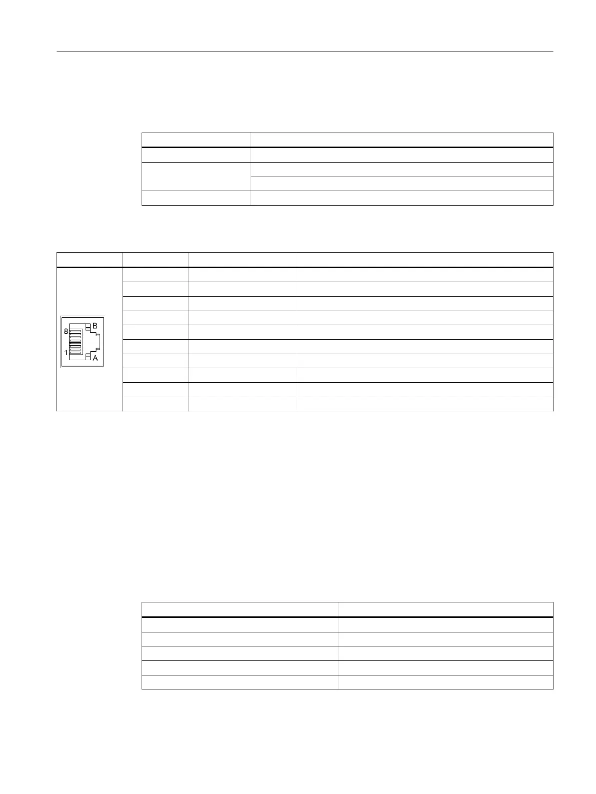
Table 9-5 Pin assignment, X100 - X103
Pin Signal name Technical specications
1 TXP Transmit data +
2 TXN Transmit data -
3 RXP Receive data +
4 - Reserved, do not use
5 - Reserved, do not use
6 RXN Receive data -
7 - Reserved, do not use
8 - Reserved, do not use
A + (24 V) Power supply
B M (0 V) Ground
DRIVE-CLiQ topology
NX components can be connected to the NCU via DRIVE-CLiQ. The following rules apply for the
wiring:
• Only one star topology is permitted between the NX and the NCU. In this way, only one NX
can be operated per DRIVE-CLiQ port of an NCU.
• DRIVE-CLiQ ports not assigned to NX can be wired to other DRIVE-CLiQ components.
• Once an NX has been connected and congured, you cannot simply insert it into a dierent
DRIVE-CLiQ port, as the addresses of the integrated drives are set permanently from the point
of view of the PLC. The following table illustrates this relation:
Table 9-6 NX PROFIBUS addresses
DRIVE-CLiQ port on the NCU Drive PROFIBUS addresses
X105 15
X104 14
X103 13
X102 12
X101 11
The following gure shows a sample topology:
Connectable components
9.1 NX10.3 / NX15.3
NCU 7x0.3B PN
Equipment Manual, 10/2020, 6FC5397-1EP40-6BA1 95
 Loading...


