2 Installation International English
MICROMASTER 440 Operating instructions
24 6SE6400-5CA00-0BP0
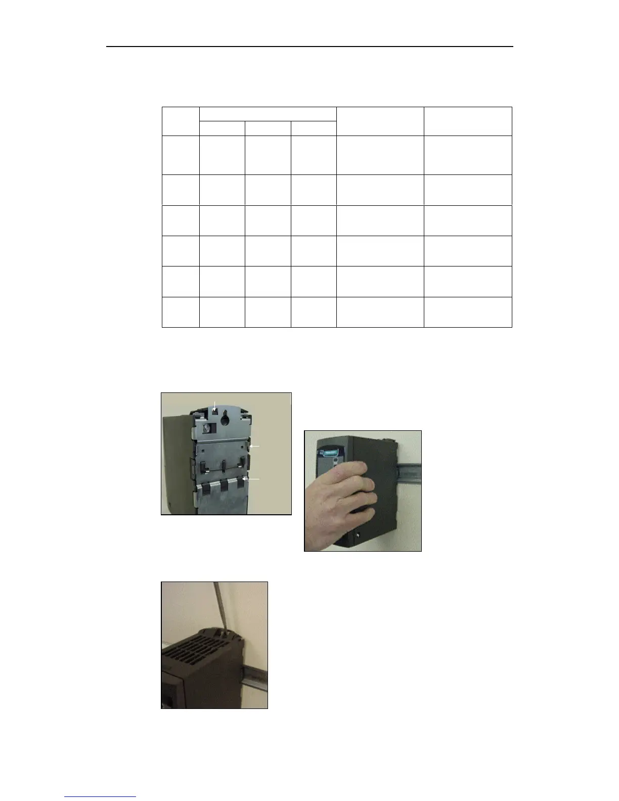
Release Mechanism
Upper DIN
rail latch
Lower DIN
rail latch
Table 2-1 Dimensions and Torques of MM440 (all frame sizes)
Overall Dimensions
Frame-
Size
Height Width Depth
Fixing Method Tightening Torque
A 173 mm 73 mm 149 mm
2 x M4 Bolts
2 x M4 Nuts
2 x M4 Washers
Connecting to DIN rail
2.5 Nm
with washers fitted
B 202 mm 149 mm 172 mm
4 x M4 Bolts
4 x M4 Nuts
4 x M4 Washers
2.5 Nm
with washers fitted
C 245 mm 185 mm 195 mm
4 x M5 Bolts
4 x M5 Nuts
4 x M5 Washers
2.5 Nm
with washers fitted
D 520 mm 275 mm 245 mm
4 x M8 Bolts
4 x M8 Nuts
4 x M8 Washers
3.0 Nm
with washers fitted
E 650 mm 275 mm 245 mm
4 x M8 Bolts
4 x M8 Nuts
4 x M8 Washers
3.0 Nm
with washers fitted
F
850 mm
with filter
1150 mm
350 mm 300 mm
4 x M8 Bolts
4 x M8 Nuts
4 x M8 Washers
3.0 Nm
with washers fitted
2.3.1 DIN Rail Mounting Frame Size A
Fitting the Inverter to the DIN Rail
1. Fit the inverter to the DIN rail using the upper
DIN rail latch.
2. Push the
inverter against
the DIN rail
and the lower
DIN rail latch
should click
into place.
Removing the Inverter from the DIN Rail
1. To disengaged the release mechanism of the
inverter, insert a screwdriver into the release
mechanism.
2. Apply a downward pressure and the lower DIN rail
latch will disengage.
3. Pull the inverter from the DIN rail.
http://nicontrols.com

 Loading...


