2 Installation International English
MICROMASTER 440 Operating instructions
30 6SE6400-5CA00-0BP0
Screening without a Gland Plate
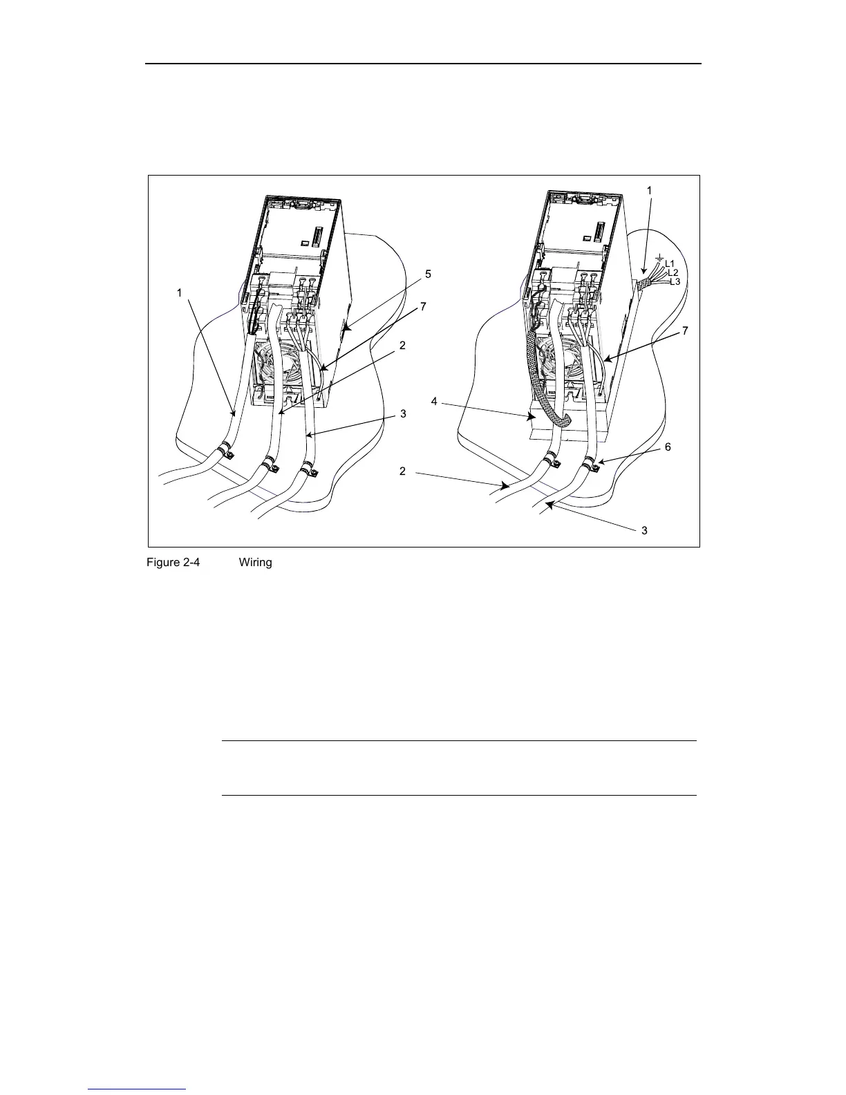
Should a Gland Plate not be available, then the inverter can be screened using the
methodology shown in Figure 2-4.
L3
L2
L1
1
1
2
5
7
7
2
3
4
3
6
Figure 2-4 Wiring Guidelines to Minimize the Effects of EMI
Legend
1 Mains power input
2 Control cable
3 Motor cable to I/O board
4 Footprint filter
5 Metal back plate
6 Use suitable clips to fix motor and control cable screens securely to metal
back plate
7 Screen cable
Note
To enhance the screening of the motor and control cables, the optional Gland
Plate can be used (not shown in Figure 2-4).
http://nicontrols.com

 Loading...


