3 Commissioning International English
MICROMASTER 440 Operating instructions
34 6SE6400-5CA00-0BP0
3.2 Commission Modes
The MICROMASTER 440 is supplied with a Status Display Panel (SDP) as the
standard operator panel. Default parameter settings cover the following
requirements:
The motor rating data; voltage, current and frequency data is keyed into the
inverter to ensure that the motor is compatible with the inverter. (A standard
Siemens motor is recommended).
Linear V/f motor speed, controlled by an analogue potentiometer.
Maximum speed 3000 min
-1
with 50 Hz (3600 min-1 with 60 Hz); controllable
using a potentiometer via the inverter’s analogue inputs.
Ramp-up time / Ramp-down time = 10 s.
If more complex application settings are required, please refer to Sections 3.2.4.1
“Quick commissioning (P0010=1)” and 5 “System Parameters” .
Note
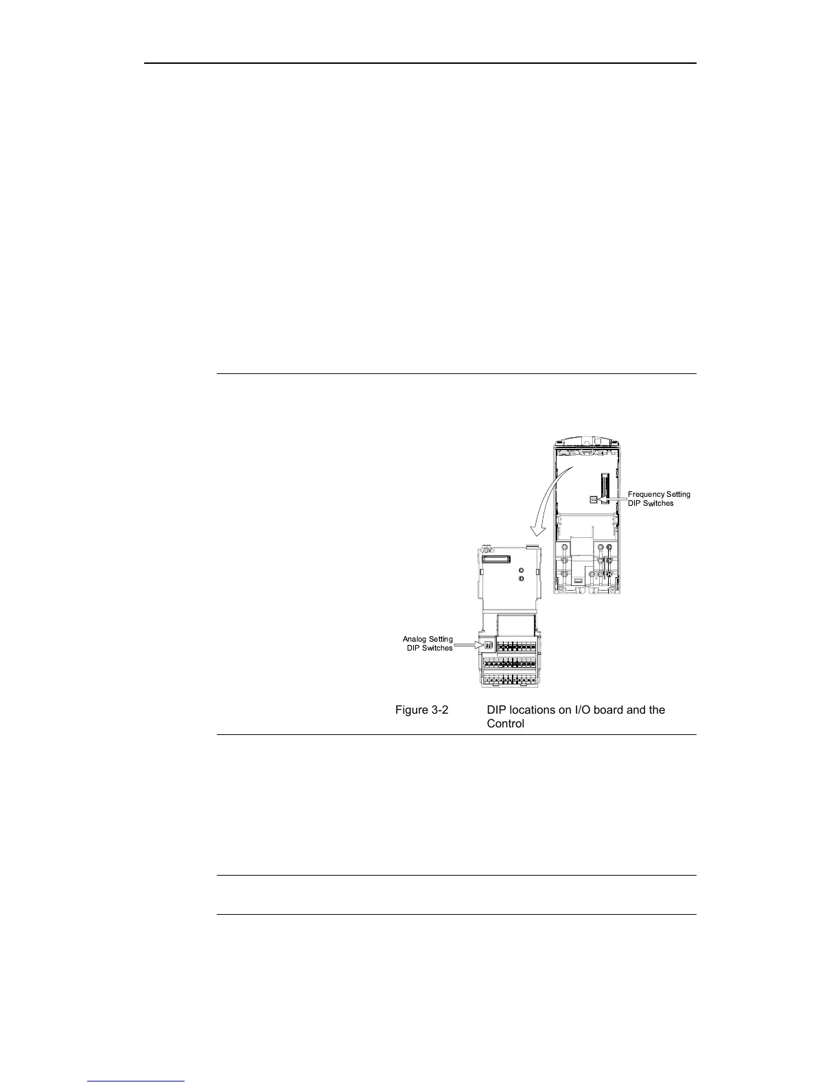
Frequency setting; the DIP switch is located on the control board, underneath the
I/O board as shown in Figure 3-2 below. The inverter is delivered as follows:
DIP switch 2:
♦ Off position:
European defaults
(50 Hz, kW etc.)
♦ On position: North
American defaults
(60 Hz, hp etc.)
DIP switch 1:
Not for customer use.
3.2.1 Reset to Factory default
To reset all parameters to the factory default settings; the following parameters
should be set as follows (BOP, AOP or Communication Option needed):
1. Set P0010=30.
2. Set P0970=1.
Note
The reset process can take up to 3 minutes to complete.
Frequency Setting
DIP Switches
Analog Setting
DIP Switches
Figure 3-2 DIP locations on I/O board and the
Control Board
http://nicontrols.com

 Loading...


