International English 3 Commissioning
MICROMASTER 440 Operating instructions
6SE6400-5CA00-0BP0
35
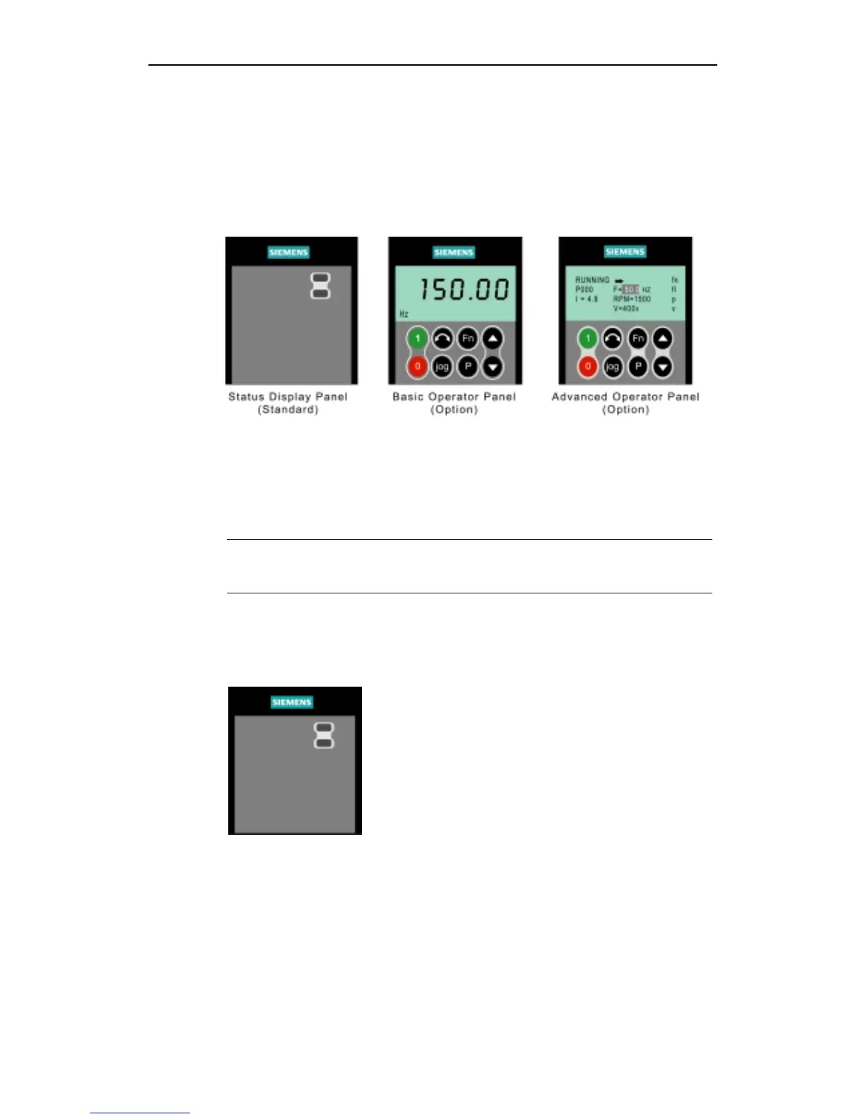
Front Panels for the MICROMASTER 440
To change the parameters of the inverter you will require one of the optional
operator panels, either the "Basic Operator Panel" (BOP) or an "Advanced
Operator Panel" (AOP). To assist in the quick and efficient changing of parameters,
commissioning software tools such as DriveMonitor can be used; this software is
supplied on the Documentation CD-ROM.
Figure 3-3 Panels available for the MICROMASTER 440 Inverter
The parameters can also be changed using one of the communication options. For
further information, please refer to the Reference Manual.
For instructions on how to exchange/replace the Operator Panels, please refer to
the appropriate Appendices in this manual.
Note
♦ The terminal layout for connecting power and control cables is shown in the
photograph on the inside of the back cover of this manual.
3.2.2 Commissioning with the Status Display Panel (SDP)
The SDP is supplied with your MICROMASTER 440 Inverter as standard. This
panel has two LEDs on the front, which indicate the operational status of the
inverter.
With the SDP the inverter can be used with its default
settings, for a number of applications. The default settings
are shown in Table 3-1.
The terminal layout is shown in the photograph of the
Control Terminal Connections on the inside of the back
cover of this manual.
Warnings and faults states on the Status Display Panel
The two LEDs on the Status Display Panel indicate the operating status of your
inverter. These LEDs also indicate various warnings or fault states. In section 6.1
the inverter states, indicated by the two LEDs are explained.
http://nicontrols.com

 Loading...


