International English 3 Commissioning
MICROMASTER 440 Operating instructions
6SE6400-5CA00-0BP0
43
Note
P0308 & P0309 are only visible if P0003 ≥ 2. Only one of the parameters is
shown depending on the settings of P0100.
P0307 indicates kW or HP depending upon the setting of P0100. For detailed
information, please see the Parameter List.
Changing motor parameters is not possible unless P0010=1.
Ensure that the inverter is configured correctly to the motor, i.e. in the above
example delta terminal connection is for 230 V.
External motor thermal overload protection
When operated below rated speed, the cooling effect of fans fitted to the motor
shaft is reduced. Consequentially, most motors require de-rating for continuous
operation at low frequencies. To ensure that the motors are protected against
overheating under these conditions, a PTC temperature sensor must be fitted to
the motor and connected to the inverter control terminals and P0601 enabled.
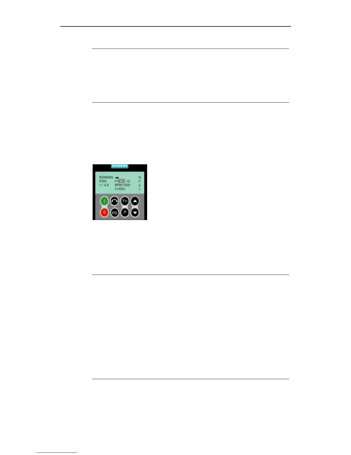
3.2.4.3 Commissioning with the Advanced Operator Panel (AOP)
The Advanced Operator Panel (AOP) is available as an
option. Its advanced features include the following:
Multilingual clear text display
Upload/download of multiple parameter sets
Multidrop capability to drive up to 30 inverters
Please refer to the AOP Manual for details or contact your
local Siemens sales office for assistance.
3.3 General operation
For a full description of standard and extended parameters, please refer to the
Parameter List.
Notes
1. The inverter does not have a main power switch and is live when the mains
supply is connected. It waits, with the output disabled, until the RUN button is
pressed or for the presence of a digital ON signal at terminal 5 (rotate right).
2. If a BOP or an AOP is fitted and the output frequency is selected to be
displayed (P0005 = 21) the corresponding setpoint is displayed approximately
every 1.0 seconds while the inverter is stopped.
3. The inverter is programmed at the factory for standard applications on
Siemens four-pole standard motors that have the same power rating as the
inverters. When using other motors it is necessary to enter the specifications
from the motor's rating plate. See Figure 3-7 for details on how to read motor
data.
4. Changing motor parameters is not possible unless P0010 = 1.
5. You must set P0010 back to 0 in order to initiate a run.
http://nicontrols.com

 Loading...


