L-2
Appendix L
• Select NO for the old system flag
driven version of Two Stage
• Select YES for the new control function
version of Two Stage
NOTE: When recompiling an older imple-
mentation of Two Stage Alarm under
CSG-M 6.07 or higher, make certain that
the New Two Stage Configuration flag is
set to NO before compiling and uploading
to the MXL-IQ.
Two Stage Signal Circuit Output
Definition
The output for all the coded audibles must
be defined on a system basis. This is done
in CSG-M from the Options, System
Message, Authorizations menu. The Zone
Coded Audible Format menu item deter-
mines the system’s Two Stage audible
definition. The following nine selections are
provided for Two Stage audibles:
Two Stage Audible - 30/120 SPM
Two Stage Audible - 30 SPM/Steady
Two Stage Audible - 30 SPM/Temporal
Two Stage Audible - Steady/Steady
Two Stage Audible - Steady/120 SPM
Two Stage Audible - Steady/Temporal
Two Stage Audible - Zone Coded/Steady
Two Stage Audible - Zone Coded/120 SPM
Two Stage Audible - Zone Coded/Temporal
Note that each selection contains a slash (/)
which separates the Stage 1 audible signal
from the Stage 2 audible signal as shown in
the following example.
Example:
Two Stage Audible - 30 / 120 SPM
Stage 1 audible
Stage 2 audible
slash
When zone coding is selected for Stage 1,
the system displays the Zone Coding
Characteristics menu. (See Figure on the
next page.) This menu allows the system
designer to program the number of rounds,
minimum number of rounds, etc. The final
state will always be STEADY no matter
what is selected in this menu.
• Zone codes must be entered on a point
by point basis.
• Zone codes will be output first by
priority, second by queue order.
• In order to have the codes sound in the
queue order only, all priorities must be
the same.
Two Stage Control Function (CSG-M)
This function has two inputs and an output
list.
The inputs are labeled Stage 1 and Stage 2.
The inputs may contain the following items:
• a device address
• function output (logic, timer, etc.)
• system flag reference
The output may only be a list of CSM-4 or
main board signal circuits. The signal
circuits referenced must be zone coded
audibles.
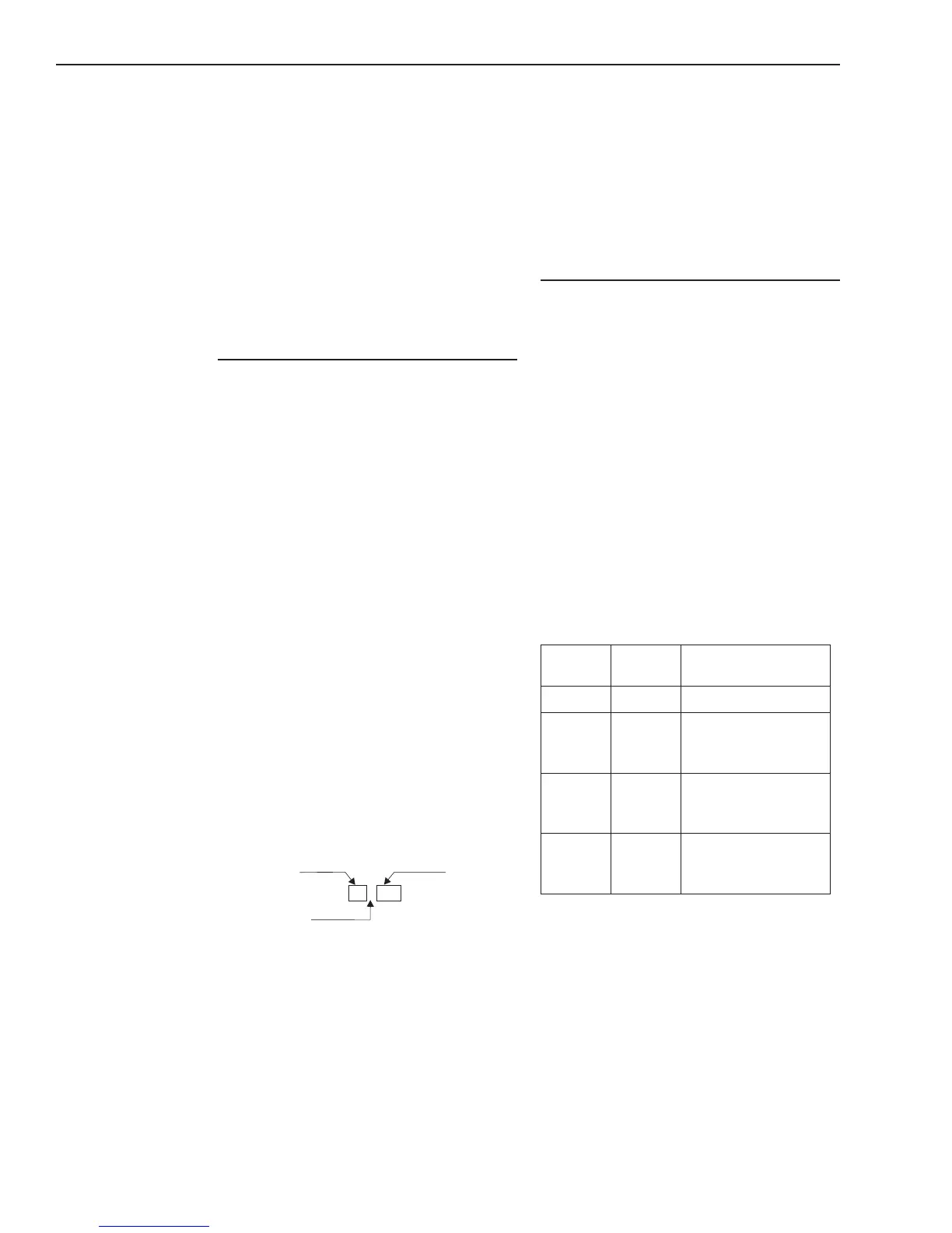
The following table describes how the Two
Stage Control Function works.
SNOITCNUFLORTNOCEGATSOWT
1egatS
tupnI
2egatS
tupnI
niselbiduAdedoC
tsiLtupuO
eslaFeslaFtneliS
eurTeslaF
angiSelbiduA1egatS
MPS03:elpmaxeroF
nidocenozroydaets
eslaFeurT
angiSelbiduA2egatS
MPS021:elpmaxeroF
laropmetroydaets
eurTeurT
angiSelbiduA2egatS
MPS021:elpmaxeroF
laropmetroydaets
Multiple Two Stage control functions may be
used in a configuration. A single coded
audible may appear on the output list of
more than one Two Stage control function.
Due to the potential conflict between the
functions controlling the same coded
output, the following rule applies to the Two
Stage control function: