RUGGEDCOM RX1400
Installation Guide
Chapter 2
Installing the Device
Mounting the Device 9
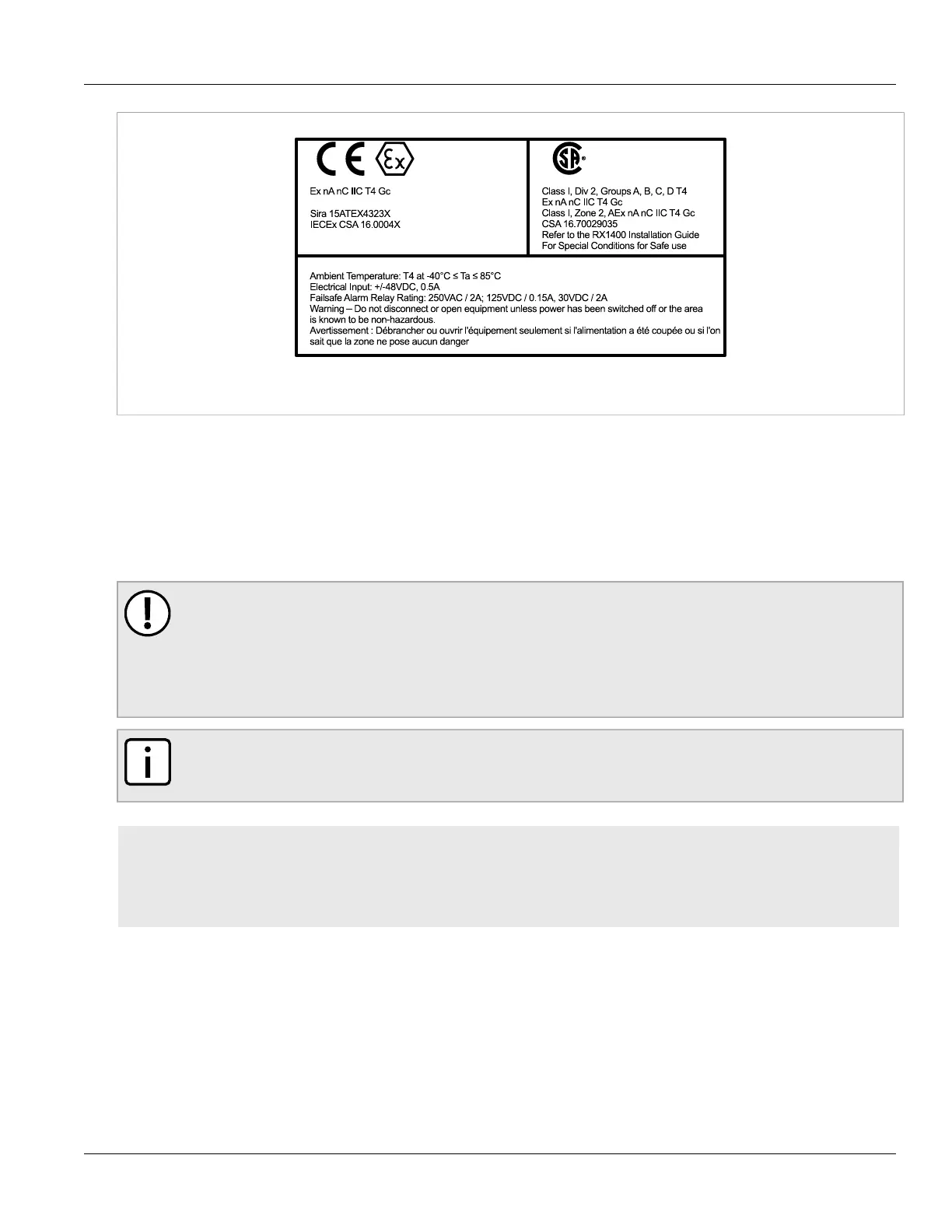
Figure2:Compliance Label (Example)
Section2.5
Mounting the Device
The RUGGEDCOM RX1400 is designed for maximum mounting and display flexibility. It can be equipped with
brackets that allow it to be installed in a 48 cm (19 in) rack, 35 mm (1.4 in) DIN rail, or directly on a panel.
IMPORTANT!
Heat generated by the device is channeled outwards to the enclosure. As such, it is recommended that
2.5 cm (1 in) of space be maintained on all open sides of the device to allow for some convectional
airflow.
Forced airflow is not required. However, any increase in airflow will result in a reduction of ambient
temperature and improve the long-term reliability of all equipment mounted in the rack space.
NOTE
For detailed dimensions of the device with either rack, DIN rail or panel hardware installed, refer to
Chapter5, Dimension Drawings.
CONTENTS
• Section2.5.1, “Mounting the Device to a Rack”
• Section2.5.2, “Mounting the Device on a DIN Rail”
• Section2.5.3, “Mounting the Device to a Panel”
Section2.5.1
Mounting the Device to a Rack
For rack mount installations, the RUGGEDCOM RX1400 can be equipped with rack mount adapters pre-installed on
the chassis.

 Loading...