RUGGEDCOM RX1400
Installation Guide
Chapter 2
Installing the Device
Connecting the Failsafe Alarm Relay 21
Section2.9
Connecting the Failsafe Alarm Relay
The failsafe relay can be configured to latch based on alarm conditions. The NO (Normally Open) contact is closed
when the unit is powered and there are no active alarms. If the device is not powered or if an active alarm is
configured, the relay opens the NO contact and closes the NC (Normally Closed) contact.
NOTE
Control of the failsafe relay output is configurable through ROX II. One common application for this
relay is to signal an alarm if a power failure occurs. For more information, refer to the ROX II User
Guide for the RUGGEDCOM RX1400.
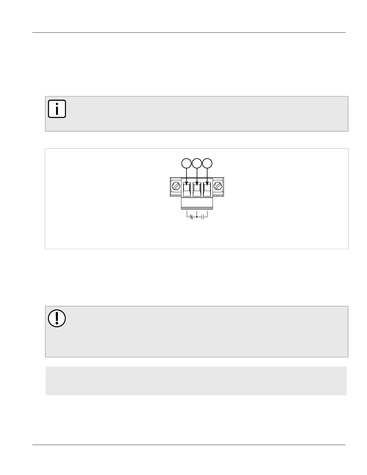
The following shows the proper relay connections.
Figure11:Failsafe Alarm Relay Wiring
1.Normally Closed 2.Common 3.Normally Open
Section2.10
Connecting Power
The RUGGEDCOM RX1400 supports a single integrated high AC/DC or low DC power supply.
IMPORTANT!
Before installing the device, note the following:
• An appropriately rated AC or DC circuit breaker must be installed.
• Use only #16 gage copper wiring when connecting terminal blocks.
• Equipment must be installed according to applicable local wiring codes and standards.
CONTENTS
• Section2.10.1, “Connecting High AC/DC Power”
• Section2.10.2, “Connecting Low DC Power”

 Loading...