Chapter 1
Introduction
RUGGEDCOM RX1400
Installation Guide
2 Description
Power Supply
• 12 to 24 VDC
• ±12 to 24 VDC
• ±48 VDC
• HI VAC/VDC
Optical SFP Pluggable Transceivers
• 2 x 1000 Mbps ports
Serial Interfaces with Isolation
• 2 x RS232/422/485 ports
Other Interfaces
• Isolated built-in power input
• RS-232 console port for local management/
diagnostics on the device
• SMA connectors for cellular, GPS and RF interfaces
• R-SMA connectors for WLAN RF interface
Section1.2
Description
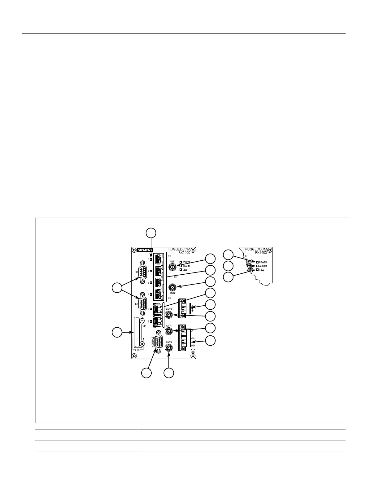
The RUGGEDCOM RX1400 features various ports, controls and indicator LEDs on the front panel for connecting,
configuring and troubleshooting the device.
Figure1:RUGGEDCOM RX1400
1.Serial Ports 2.Access Plate 3.Port Status LEDs 4.ANT1 Port 5.Fast Ethernet Ports 6.ANT2 Port 7.SFP Transceiver Ports
8.Failsafe Alarm Relay 9.ANT3 Port 10.ANT4 Port 11.Power Supply Terminal Block 12.RS232 Serial Console Port (DB9) 13.ANT5
Port 14.POWER LED 15.ALARM LED 16.CELL LED
POWER LED Illuminates when power is being supplied to the device.
ALARM LED Illuminates when an alarm condition exists.

 Loading...