① RJ45 Ethernet port (with display LEDs)
② Slots for CPU modules
③ Slots for communications modules. These are equipped with a protective cover for unused
slots.
④ USB port
⑤ Power supply connection 24 V DC
⑥ Fastening hole
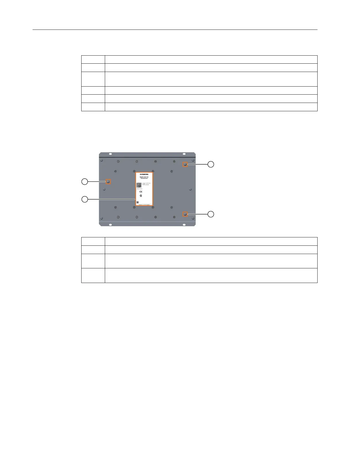
Design of the rear
The following gure shows the rear of the rack:
① Screw for grounding the reference potential
② Nameplate (Page 22)
③ Screw for connecting the shielding of the network cables X2, X2.1 and X2.2 to the metal
enclosure
④ Screw for connecting the shielding of the network cables X1, X1.1 and X1.2 to the metal
enclosure
3.3.2 CPU module
Denition
In the CN 4100 communication system, only the CN 4100 CPU is used as the central control
module.
System overview
3.3 Basic components of the system
CN 4100 Communication System
Equipment Manual, 10/2021, A5E50871363-AA 13