8.1.2.3 Switching o the CPU module
Requirement
• You have adhered to the basics for mounting.
• The supply voltage is connected to the rack.
• The CPU module has been started.
Procedure
Press and hold the reset button for 6 seconds.
Result
The system powers down together with the CPU module.
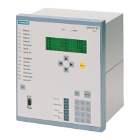
8.1.3 Status LEDs of the CPU module
Denition
The status LEDs of the CPU module provide information about the operating mode of the CPU
or indicate errors.
Meaning for redundant CPU modules
The following table shows the status LEDs and their meaning.
RTC = Runtime Container
LED Master module Standby module
Continuous light Flashes Continuous light Flashes
Power supply Power supply OK Power supply OK
RUN RTC running RTC running
STOP RTC stopped RTC stopped
Master RTC is master
Cycle / Engineering run‐
ning
LED is o
Standby RTC has detected stand‐
by
Synchronization stand‐
by
RTC in standby mode Synchronization stand‐
by
AH failure Plant network discon‐
nected
Plant network discon‐
nected
Operation
8.1 Operating the CPU module
CN 4100 Communication System
Equipment Manual, 10/2021, A5E50871363-AA 53