Design
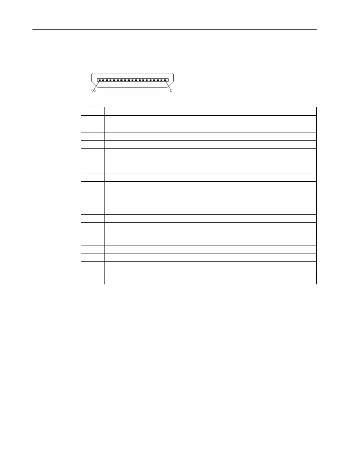
Pin Description
1 TMDS Data2+
2 TMDS Data2 shield
3 TMDS Data2−
4 TMDS Data1+
5 TMDS Data1 shield
6 TMDS Data1−
7 TMDS Data0+
8 TMDS Data0 shield
9 TMDS Data0−
10 TMDS Clock+
11 TMDS Clock shield
12 TMDS Clock−
13 CEC
14 Reserved (HDMI 1.0-1.3c), Utility/HEC/ARC (Optional, HDMI 1.4+ with HDMI Ethernet channel
and audio return channel)
15 SCL (Line I²C "Serial Clock" for DDC)
16 SDA (Line I²C "Serial Data" for DDC)
17 DDC/CEC/ARC/HEC ground
18 +5 V (min. 0.055 A)
19 Hot Plug Detect (all versions) and HEC/ARC (optional, HDMI 1.4+ with HDMI Ethernet channel
and audio return channel)
B.2.2 Micro-HDMI port of the CPU module
Denition
The Micro-USB port is required for the setup and maintenance of the CPU module.
Description
The CPU module is equipped with a USB port (type B).
Data connections
B.2 Connections of the CPU module
CN 4100 Communication System
Equipment Manual, 10/2021, A5E50871363-AA 71