Functions
8.2 Time stamping the input signals with IM 153-2
ET 200M
156 Operating Instructions, 12/2008, EWA-4NEB780600602-08
8.2.4.7 Structure of the IM 153-2 messages
The IM 153-2 makes available 15 data records for saving stamped input signals (signal
messages) and special messages (DS 100 to DS 114). A maximum of 20 signal and special
messages each consisting of 12 bytes can be saved in a data record.
Structure of the message frame header
Each message frame with a data record has 4 bytes of header data:
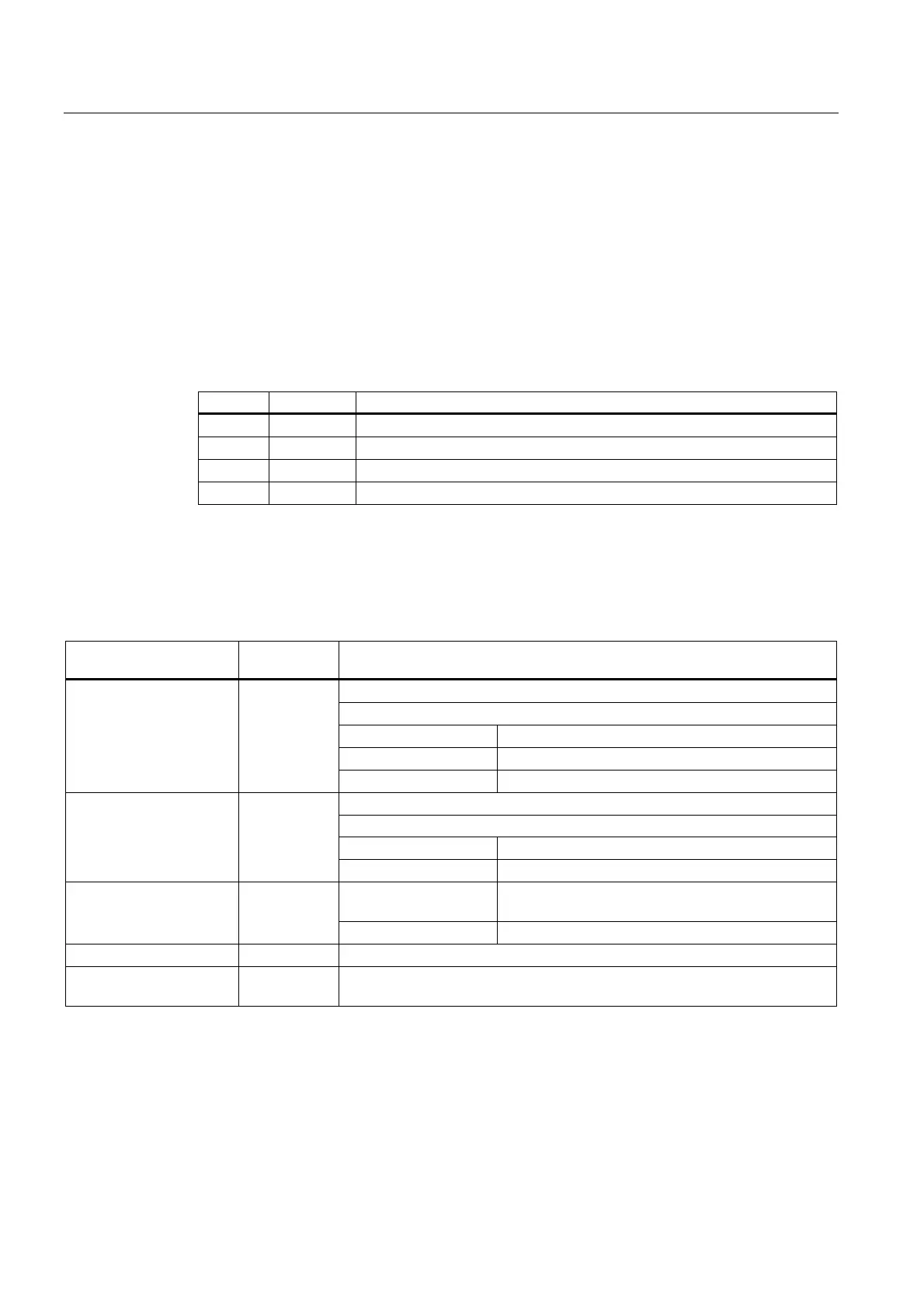
Table 8- 5 Header data of the IM 153-2 message frame (example)
Byte Contents Meaning
0 5Eh Read data record
1 00h IM 153-2 slot
2 64h Number of the data record (e.g. 100 dec.)
3 0Ch Number of the following bytes (e.g. 12 dec.)
Structure of the signal message
A signal message can come from modules on the slots 4 to 11. It is structured as follows:
Table 8- 6 Structure of the signal message
Meaning Number of
bytes
Remarks
Together with the channel number for addressing the digital signal
Range of values:
0 … 3 Unassigned
4 … 11 Slot number of the DI module
Slot number of the DI
module
1
12 … 255 Unassigned
Together with the slot number for addressing the digital signal
Range of values:
0 … 15 Channel number of the DI module
Channel number of the DI
module
1
16 … 255 Unassigned
Bit 7 1: Signal incoming
0: Signal outgoing
Signal status 1
Bit 6 … Bit 0 Unassigned
Reserved 1 Unassigned
Time of the signal change 8 (2 DW) Time stamp in ISP-format
(refer to table below for structure)

 Loading...