ET 200M
Operating Instructions, 12/2008, EWA-4NEB780600602-08
185
Interrupt, error and system messages
9
9.1 PROFIBUS DP
9.1.1 Diagnostics with LED display
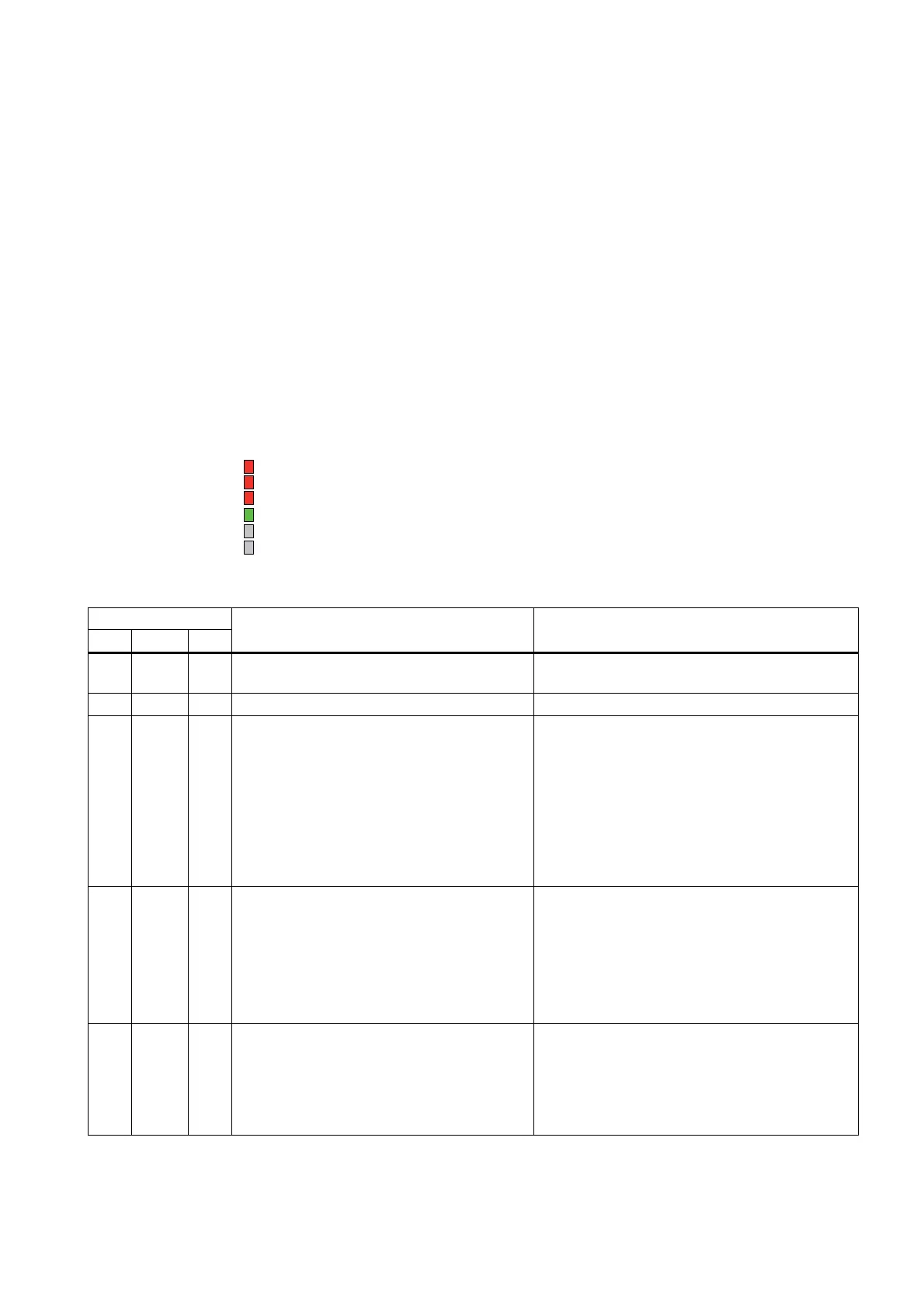
Status and error displays of the IM 153-1
21 6XSSO\ YROWDJH DYDLODEOH *UHHQ
%) (UURU RQ WKH 352),%86'3 5HG
6) *URXS HUURU 5HG
6)
%)
21
Table 9- 1
LEDs
SF BF ON
Meaning Remedy
off off off No voltage on the IM 153-1 or there is a
hardware fault with the IM 153-1.
Switch on the power supply module or replace the
IM 153-1.
* * On There is voltage on the IM 153-1. —
* flashes on IM 153-1 is incorrectly configured - no data
exchange is taking place between the DP
master and the IM 153-1.
Causes:
• Configured and set PROFIBUS address is
incorrect
• Faults on the bus
• Check the IM 153-1.
• Check the configuration and parameter
settings.
• Check the PROFIBUS address on the IM 153-
1 and in the STEP 7 project.
• Check the cable length with reference to the
baud rate.
• Check the settings for the terminating
resistors.
* on on no connection to the DP master (search baud
rate)
Causes:
• the bus communication via PROFIBUS DP
to the IM 153-1 has been interrupted
Check the bus configuration.
• Check to see if the bus connector is inserted
properly.
• Check whether the bus cable to the DP master
is defective.
• Switch off and on the on / off power switch for
the 24 V DC on the power supply module.
on flashes on The configured structure of the ET 200M
doesn´t tally with the actual structure of the ET
200M
Check the PROFIBUS address and the
configuration of the ET 200M to see if a module is
missing, faulty or if there is a non-configured
module.
Check the configuration (e.g. with
COM PROFIBUS
or
STEP 7
).

 Loading...