Brief instructions on commissioning
2.1 Commissioning on PROFIBUS DP
ET 200M
Operating Instructions, 12/2008, EWA-4NEB780600602-08
23
Number Item Order number (Siemens)
1 Side cutters and wire stripping tools commonly available
1 Tool for crimping wire-end ferrules commonly available
Approx.
2 m
Stranded wire with 1 mm
2
cross section with
appropriate wire end ferrules, type A, length 6 mm
commonly available
2 one-pin on button commonly available
1 24 V indicator lamp commonly available
2.1.2 Mounting the ET 200M
Procedure
1. Mount the rail on a firm base so that there is at least 40 mm clearance above and below
the rail.
2. Starting from the left side, mount the individual modules on the rail (plug in the bus
connectors (not for PS 307 and the last module) – engage – swing in – screw down).
Observe the following sequence:
– Power supply PS 307
– Interface module IM 153-2
– DI module SM 321
– DO module SM 322
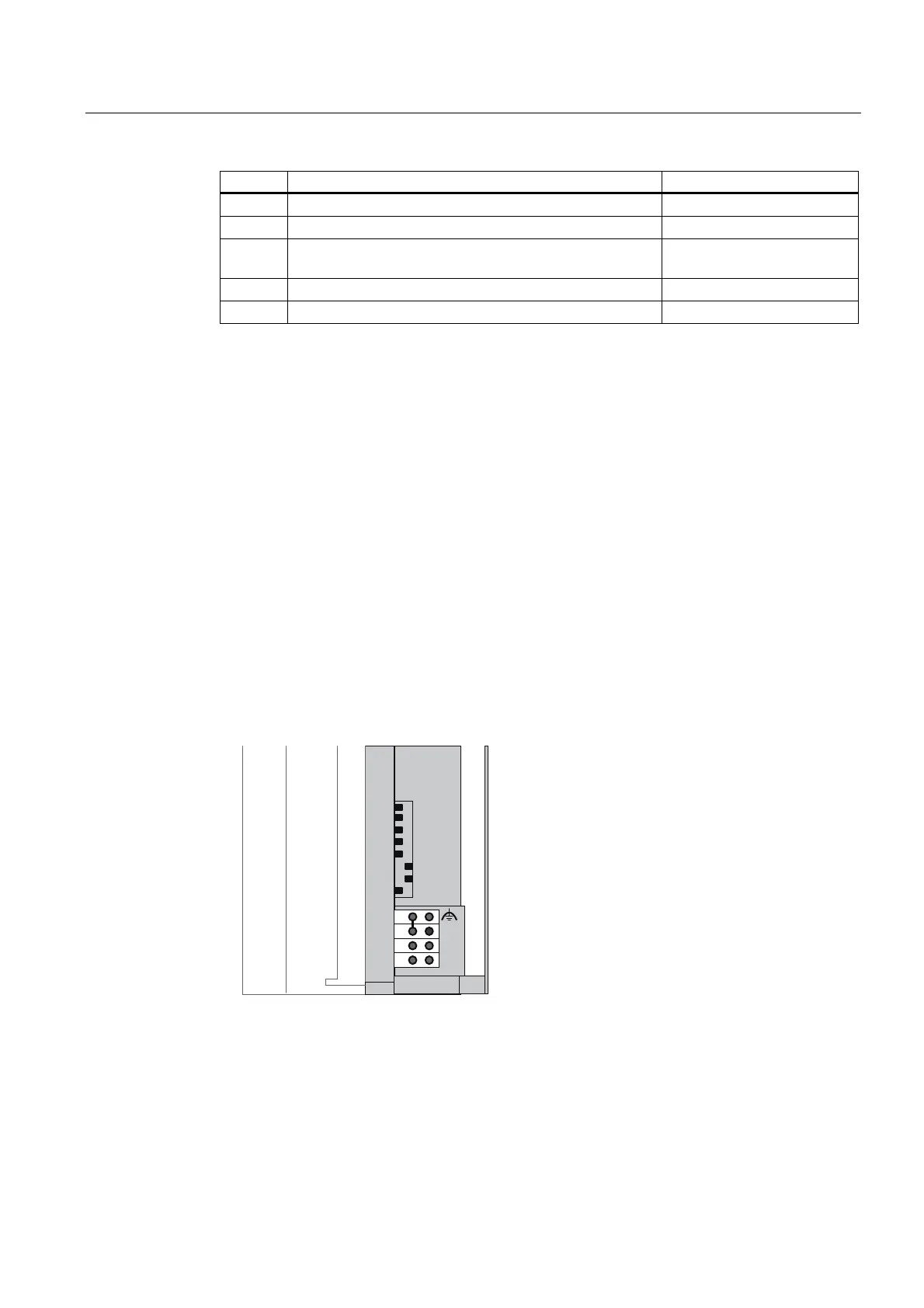
3. Set PROFIBUS address 3 on the interface module IM 153-2.
%86
21
0
/
0
'&9
$''5(66
,0
Figure 2-2 Setting PROFIBUS address 3

 Loading...