Installation
4.2 Installation
ET 200M
Operating Instructions, 12/2008, EWA-4NEB780600602-08
63
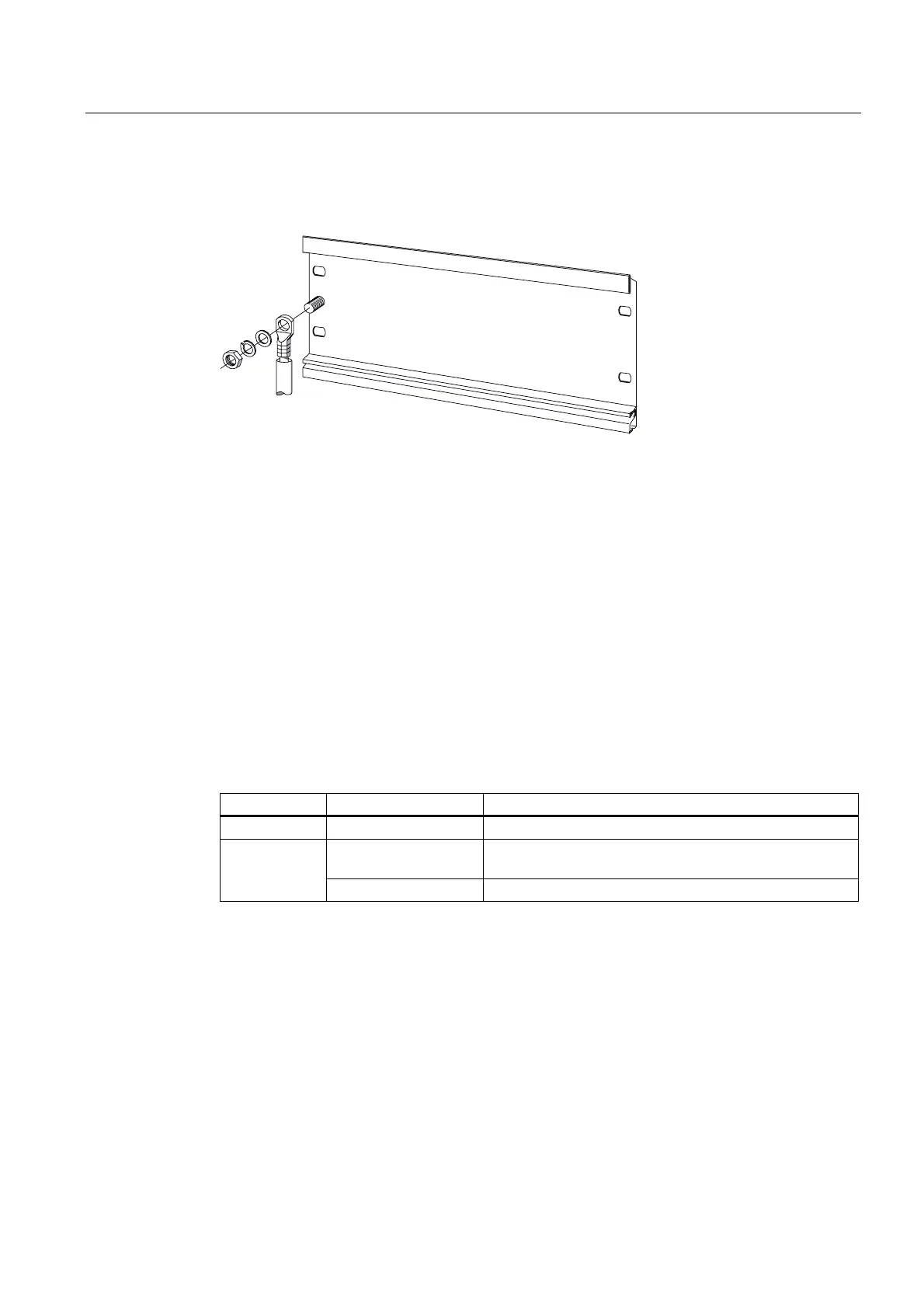
Connection of protective conductor
The following figure shows you how to connect the protective conductor to the rail.
Figure 4-2 Connecting the protective conductor to the rail
See also
Clearance Measurements (Page 41)
4.2.3 Installing modules on the mounting rail (standard installation)
Accessories
The accessories you need for installation are included with the modules. The appendix
"Order Numbers for ET 200M (Page 247)" contains a list of accessories and spare parts with
the corresponding order numbers.
Table 4- 2 Module accessories
Module Included accessories Description
IM 153-x 1 x slot number label For assigning slot numbers
Bus connectors For establishing the electrical connections between the
modules
Signal module
(SM)
Labeling strip For labeling the input and output points on the module