Installation
4.2 Installation
ET 200M
62 Operating Instructions, 12/2008, EWA-4NEB780600602-08
Fixing Screws
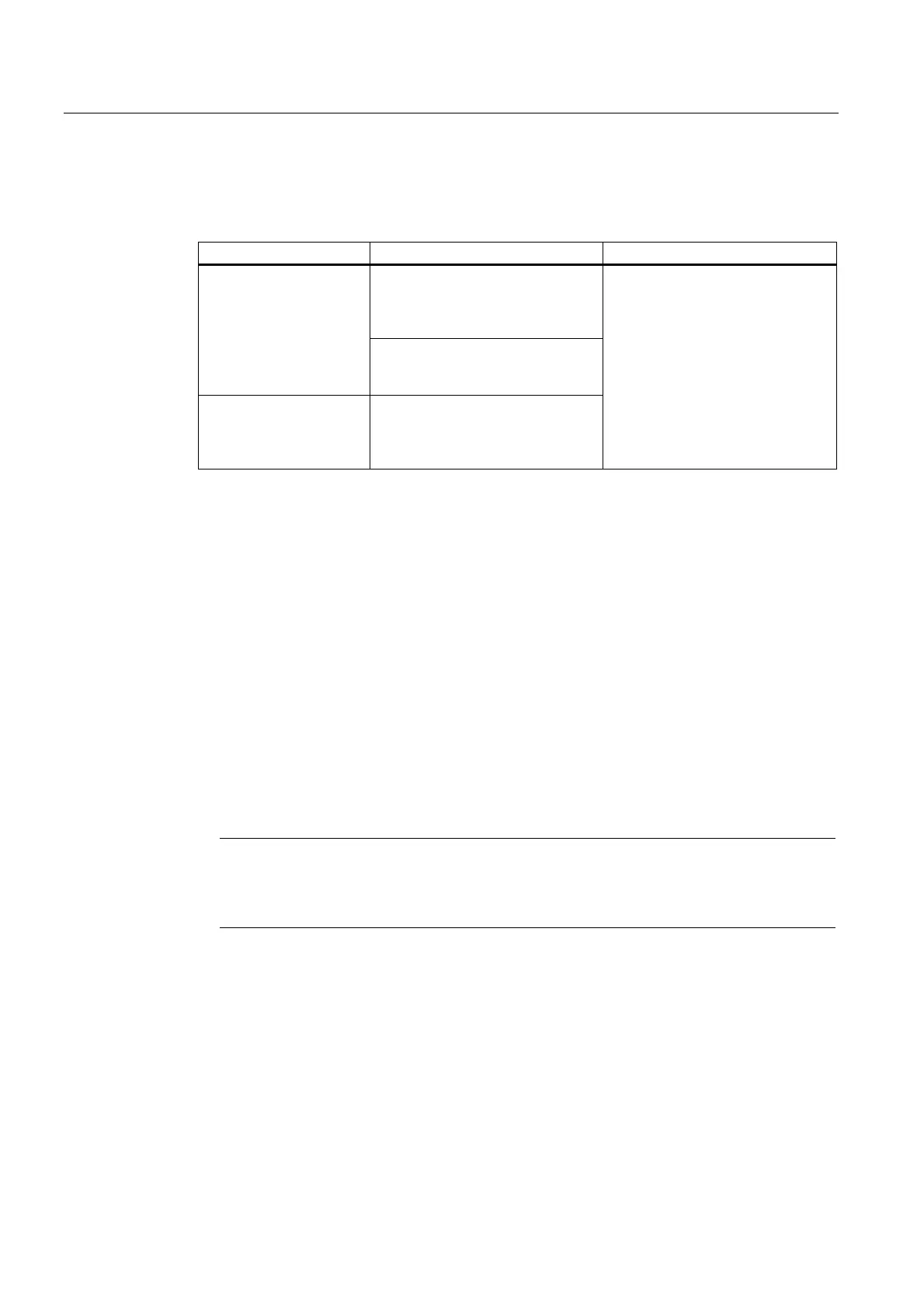
You have a choice of the following screw types for fixing the rail.
For … you can use ... Description
Fillister head screw M6 in
accordance with
ISO 1207 / ISO 1580
(DIN 84 / DIN 85)
Outer fixing screws
Hexagon head screw M6 in
accordance with ISO 4017
(DIN 4017)
additional fixing screw
(only 2-meter rail)
Fillister head screw M6 in
accordance with
ISO 1207 / ISO 1580
(DIN 84 / DIN 85)
Choose a suitable screw length for
your configuration.
You also require washers 6.4 in
accordance with ISO 7092
(DIN 433).
Installing the mounting rail
To install the rail, proceed as follows:
1. Choose a position for the rail that leaves enough room to install it properly and enough
space to cope with the temperature rise of the modules. Observe the minimum clearance
distances of 40 mm above and below the rail.
2. Connect the rail to the base (screw size: M6).
Is this base a grounded metallic plate or a grounded device supporting plate?
If not: No particular steps are required.
If so: Ensure there is a low-impedance connection between the rail and the base. In the
case of painted or anodized metals, for instance, use a suitable contacting agent or
contact washers.
3. Connect the rail to the protective conductor. An M6 screw is provided for this purpose on
the rail.
Minimum cross-section of the cable to the grounding wire: 10 mm
2
.
Note
Ensure that your connection to the protective conductor is low-impedance (see the
following figure). If the ET 200M is mounted on a hinged rail, for example, you must use a
flexible cable to establish the connection to the protective conductor.
 Loading...