Functions
8.6 Isochrone mode
ET 200M
Operating Instructions, 12/2008, EWA-4NEB780600602-08
173
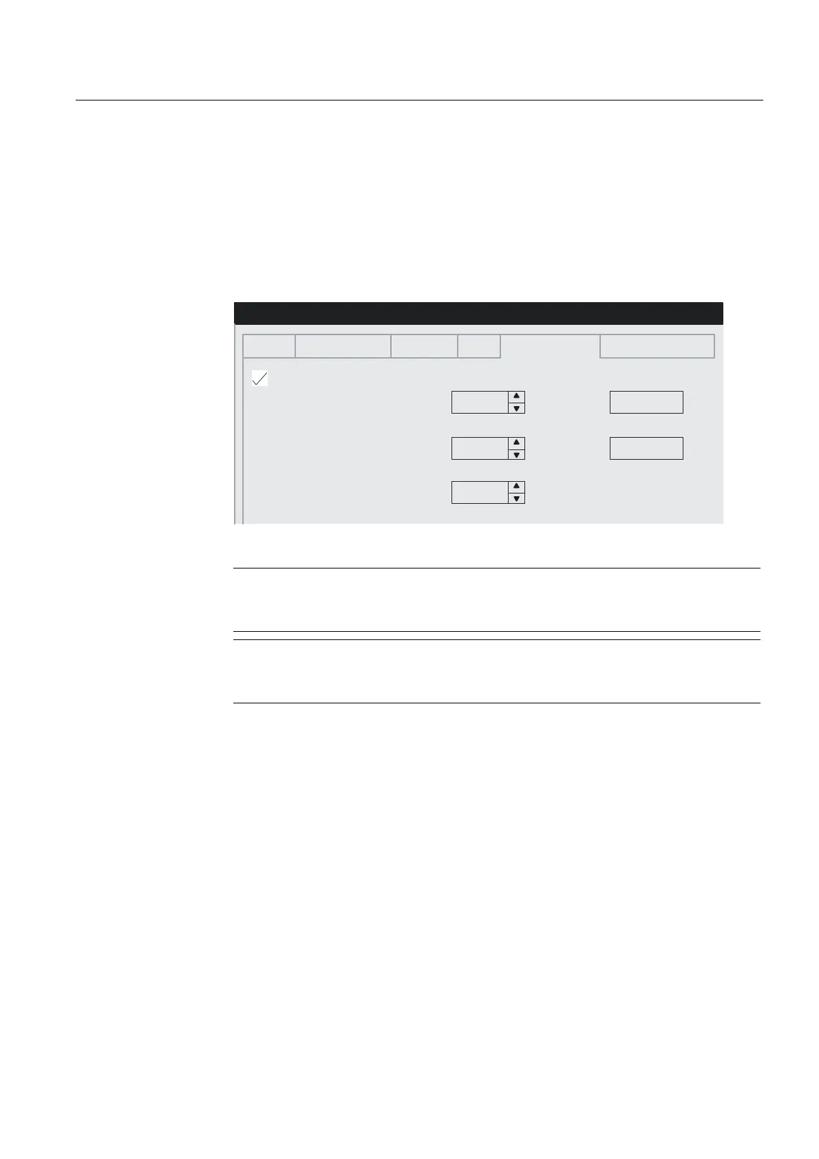
3. Settings on the DP slave:
"Object properties" of the DP slave > tab "Isochrone mode"
– Enable "Synchronize DP slave to constant bus cycle time for DP cycle".
– Enter the times Ti and To (if "Times Ti and To same for all slaves" has not been set on
the DP master system). Recommendation: Adopt the standard settings for Ti and To.
– Select the modules to be synchronized and in the "Addresses" tab assign the process
image partition that has been defined in the CPU.
PV PV
PV PV
PV
'3VODYHSURSHUWLHV
*HQHUDO 7LPHVWDPSLQJ ,GHQWLILFDWLRQ 6SHFLDO ,VRFKURQHPRGH 7LPHV\QFKURQL]DWLRQ
6\QFKURQL]H'3VODYHRQHTXLGLVWDQW'3F\FOH7L7RVDPHIRUDOOVODYHV
7LPH7LUHDGSURFHVVYDOXHV
PLQ PVPD[ PV
7LPH7RRXWSXWSURFHVVYDOXHV
PLQ PVPD[ PV
(TXLGLVWDQW'3F\FOH
PLQ PVPD[ PV
%ORFNV
%ORFNV
Figure 8-23 DP slave properties dialog box
Note
If, in the "Edit" menu you click on "Isochrone mode", you will be shown a configuration
overview of the isochrone modules.
Note
An ET 200M with analog input / output modules does not work in isochrone mode if
the format of the analog values has been configured as SIMATIC S5.
4. Setting up a user program:
– Setting up the OB 61.
– At the beginning of the OB 61 the SFC 126 must be called in order to update the part
process image of the inputs.
– At the end of the OB 61 the SFC 127 must be called in order to update the part
process image of the outputs.
– Here, use the part process image that has been configured in the CPU ("Synchronous
cycle interrupts" tab).

 Loading...