Interrupt, error and system messages
9.1 PROFIBUS DP
ET 200M
Operating Instructions, 12/2008, EWA-4NEB780600602-08
201
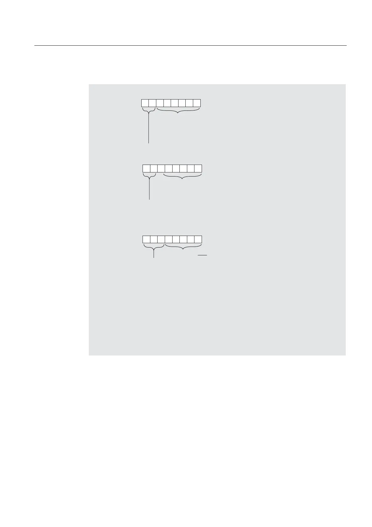
Structure of the channel-related diagnostic
%\WH
%\WH
%\WH
%LWQR
%
WR
%
&RGHQXPEHURIWKHPRGXOHWKDW
VXSSOLHVWKHFKDQQHOVSHFLILFGLDJQRVLV
([DPSOH6ORWKDVWKHFRGHQXPEHU
6ORWKDVWKHFRGHQXPEHUHWF
DVRIE\WH
&RGHIRUFKDQQHOVSHFLILFGLDJQRVLV
%
WR
%
1XPEHURIWKHFKDQQHORUFKDQQHOJURXS
WKHGLDJQRVLVVXSSOLHV
%LWQR
,QSXW2XWSXW
%
,QSXW
%
(GLWLRQ
%
,QSXW2XWSXW
%LWQR
(UURUW\SH LQDFFRUGDQFHZLWK352),%86VWDQGDUG
UHIHUWRWKHIROORZLQJWDEOHV
&KDQQHOUHVROXWLRQ
%
%LW
%
ELWV
%
ELWV
%
%\WH
%
:RUG
%
ZRUGV
WR
1H[WFKDQQHOVSHFLILFGLDJQRVLVPHVVDJH
$VVLJQPHQWDVZLWKE\WHWRE\WH
0D[%\WHZLWK,0
2U%\WHZLWK,0
Figure 9-6 Structure of the channel-related diagnostics
Overflow of channel-related diagnoses
If there are more channel-related diagnoses than can be shown in the slave diagnosis, then
the bit 7 "diagnosis overflow" is set in the station status 3.
The channel-related diagnoses that are not transferred with the message frame are not lost.
They follow on to the slave diagnosis as soon as other channel-specific diagnoses that are
entered in the diagnostic frame have gone.
Once the "diagnosis jam" has been worked off, the bit 7 "diagnostic overflow" is reset.

 Loading...