Interrupt, error and system messages
9.1 PROFIBUS DP
ET 200M
Operating Instructions, 12/2008, EWA-4NEB780600602-08
215
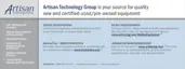
Hardware interrupt of digital input modules
%\WH[
%\WH[
(GJHFKDQJHFKDQQHORIWKHPRGXOH
(GJHFKDQJHFKDQQHORIWKHPRGXOH
(GJHFKDQJHFKDQQHORIWKHPRGXOH
(GJHFKDQJHFKDQQHORIWKHPRGXOH
(GJHFKDQJHFKDQQHORIWKHPRGXOH
(GJHFKDQJHFKDQQHORIWKHPRGXOH
%\WHV[DQG[ 0RGXOHVSHFLILFLQIRUPDWLRQ
UHIHUWRWKHGHVFULSWLRQRIWKHUHVSHFWLYHPRGXOHV
Figure 9-17 Structure as of byte x+4 for hardware interrupt (digital inputs)
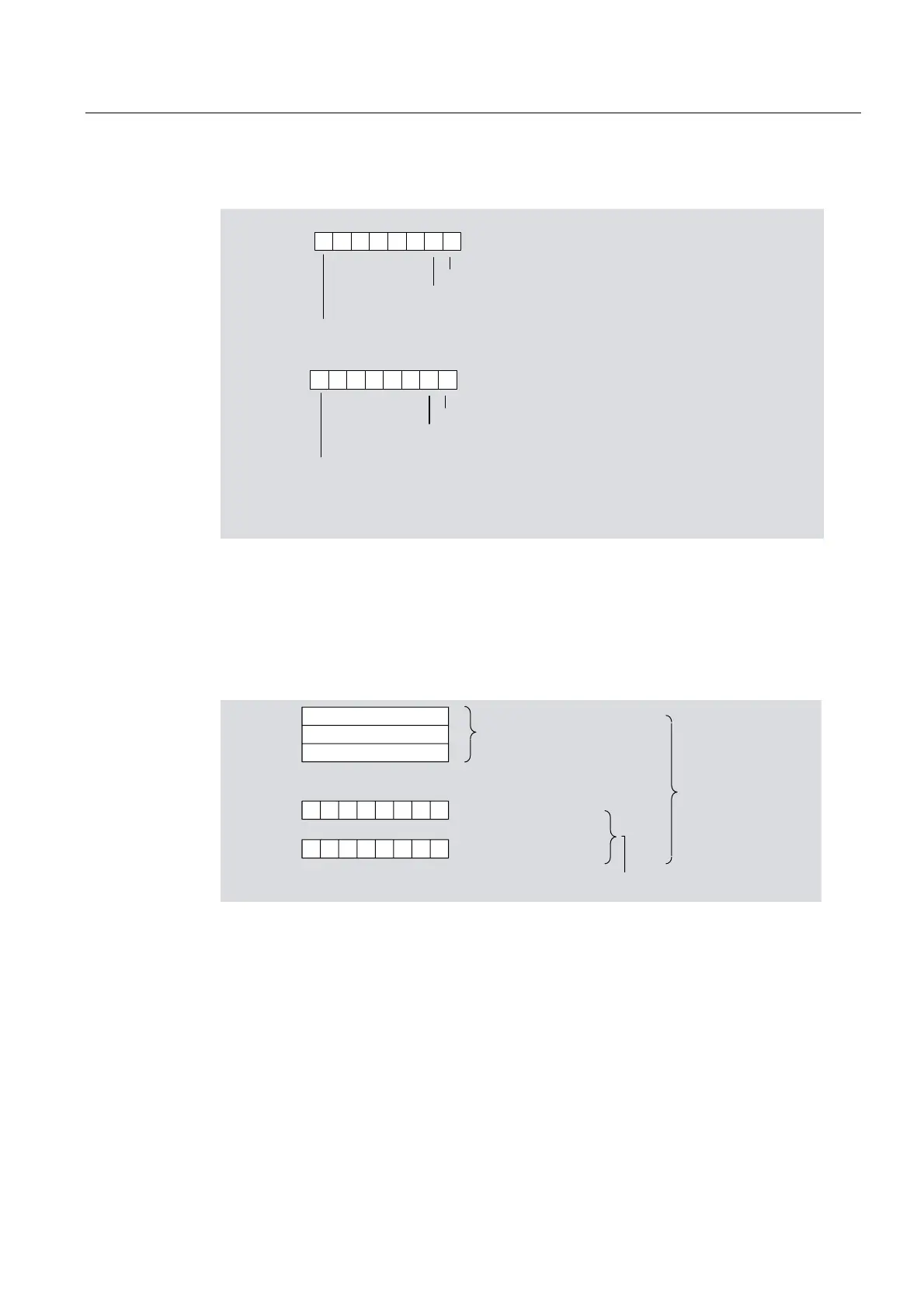
Removing / insertion interrupt
Bytes x+4 to x+8 show the code of the module that has been inserted or removed. The
codes for the individual modules can be found in the GSD file. You can see whether or not
the module has been inserted or removed from the interrupt type in byte x+1.
%\WH[
%\WH[
%\WH[
%\WH[
%\WH[
QRWDSSOLFDEOH
7\SHFRGHRIWKH
0RGXOHKLJKE\WH
7\SHFRGHRIWKH
0RGXOH/RZ%\WH
5HIHUWR*6'ILOH
6.)
LGHQWLILHU
Figure 9-18 Structure as of byte x+4 for removing / inserting interrupt
See also
Structure of slave diagnosis (Page 191)
Arrangement of the modules for the function "Change During Operation" and / or
"Redundancy" (Page 44)

 Loading...